
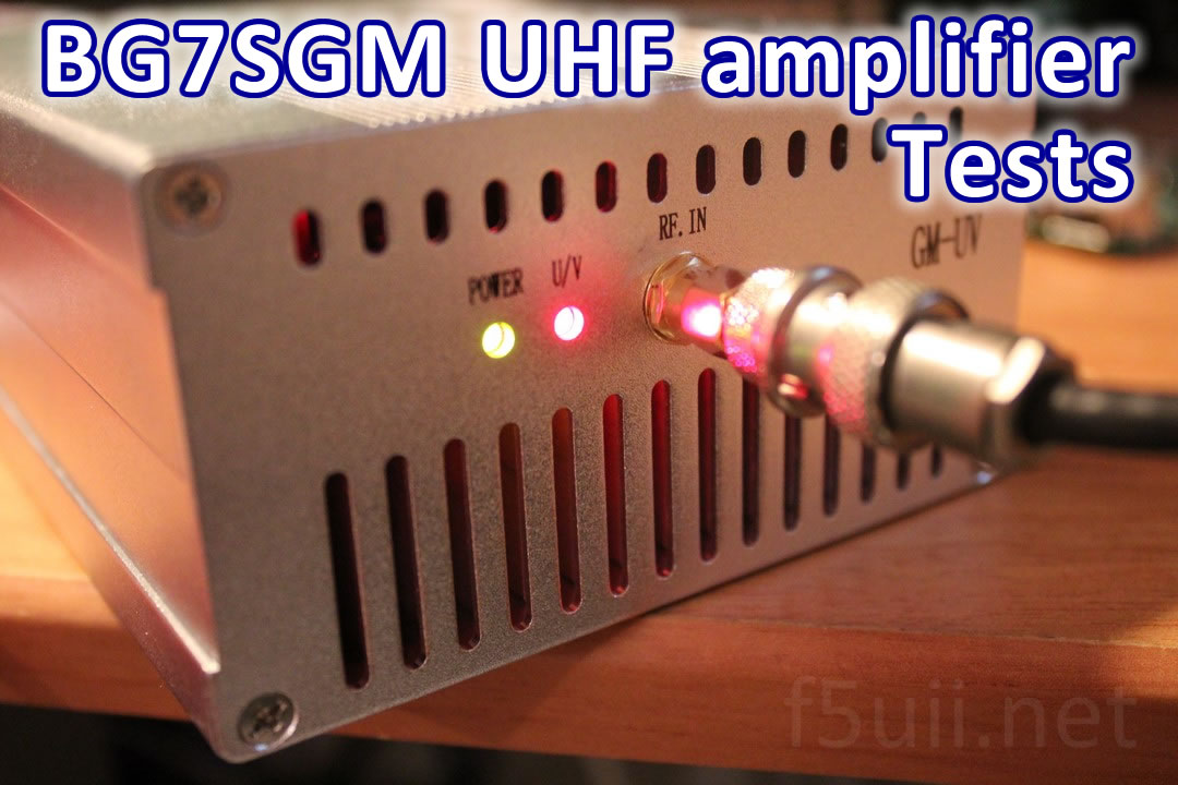
I just bought a UHF amplifier from China. Here is a brief report of its characteristics.
The order
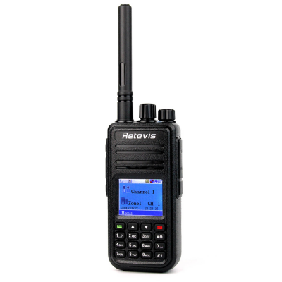
Available on the historic online auction website, I chose to buy this 50-watt UHF amplifier to improve the transmission of my mobile station, for the time being equipped with a 5 Watts MD380 (or RETEVIS RT3) maximum. Curiously the technical description of the product has nothing to do in my opinion with what the amplifier is. It is also available on other sales sites. It was delivered to me exactly 10 calendar days after its online order. Reception is contracted to the postman.
The package arrived pretty battered. Inside, the case packed in several layers of bubble paper, accompanied by a long 1.25 meter power cord. The figure “48” is written to the felt on the paper bubbles.

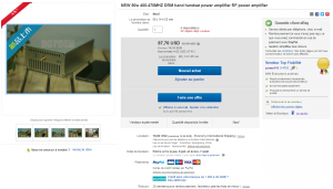
Ebay – 400-470 DMR power amplifier
Connection
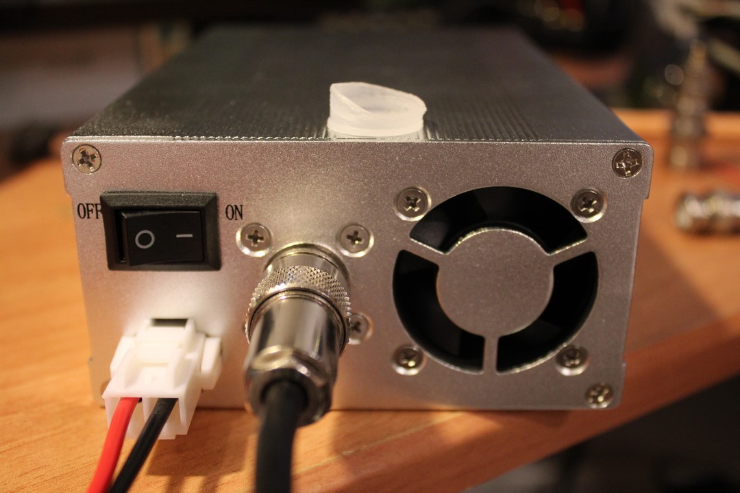
After unpacking, let’s see how the case looks.
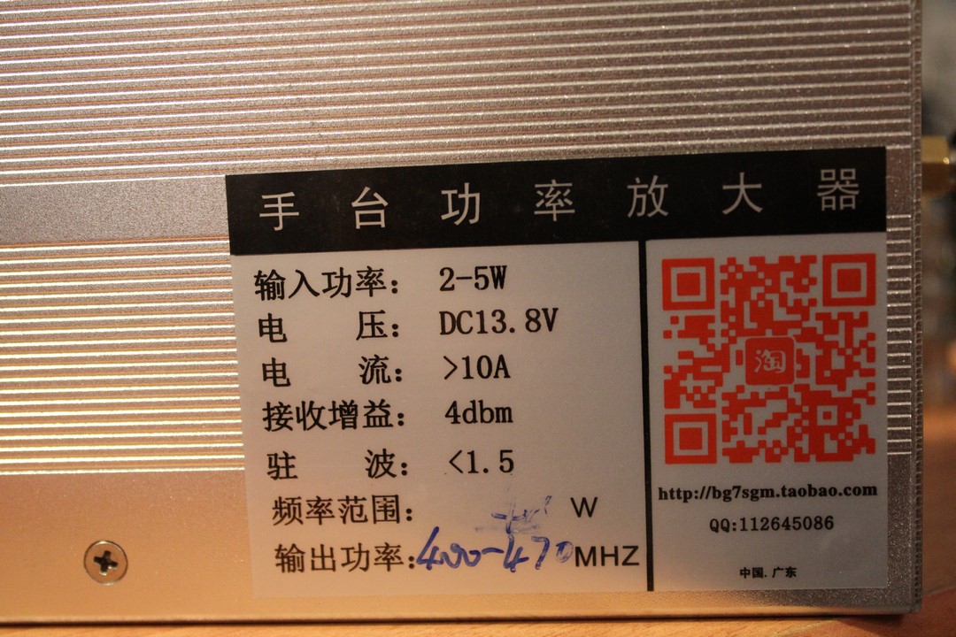
The characteristics label of the amplifier bg7sgm
The first thing we noticed: the side plates carrying the plugs were somewhat distorted. This is certainly due to the fact that the two half-shells are slightly offset to one another. Effect of transport or inaccurate assembly?
The input channel is a female SMA jack. The output is a female PL PLC SO259. I would have preferred to see a N or BNC connector.
I am trying to screw an SMA-BNC adapter into the SMA socket. Surprise: The socket turns a quarter turn … It will be necessary to open the side panel.
The open case
The four screws deposited, I find a fault. The socket is desoldered, it turns around the central pine that remains welded. One leg of the plug is broken. The center female pin is no longer in its proper position in the insulation. The spindle retreated, and the body advanced! It is certain that, as it stands, the contact with the plug will not be made.
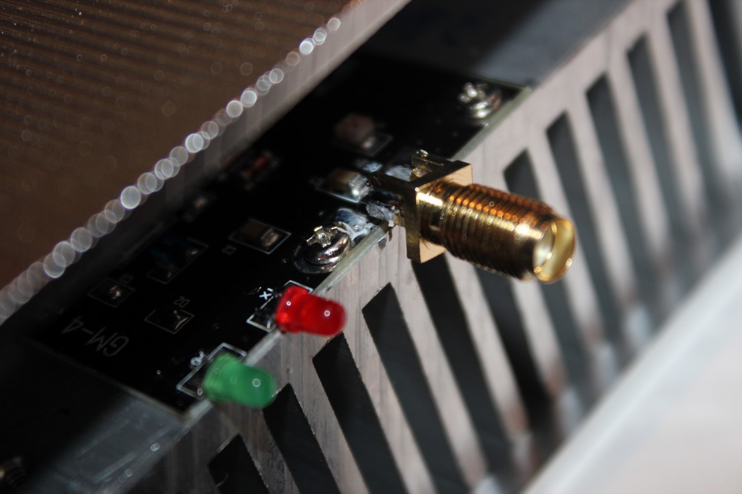
Input RF SMA connector, desoldered and with broken leg
The soldering iron is heated and I correct the problem by successfully pushing the center female pin in its insulation. The whole is re-soldered on the PCB. The box being open, is an opportunity to show you its contents.
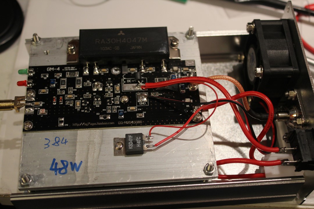
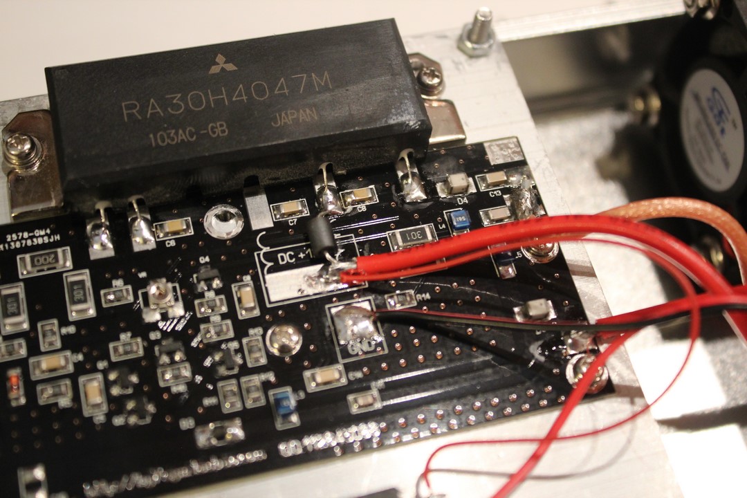
50-watt amplification with MITSUBISHI RA30H4047M
The amplifier contains a Mitsubishi RA30H4047M amplifier module operating in the range 400 to 470 MHz. Here is the RA30H4047M MITSUBISHI datasheet. There is a handwritten “48W” for the power measured at the factory ?
The module is fixed on a large radiator integrated in the case. A thermostat mounted on the radiator operates to activate the blower when the temperature exceeds 40 ° C.
Amplifier Tests
Let us see the behavior of the amplifier working in real situation. I add banana plugs to the power cord. I connect my transmitter DMR (Retevis RT3, equivalent MD380) on one side and the external antenna on the other (remove the protective cap Hi …).
Input side of the UHF amplifier, equipped with an SMA socket.
The antenna is connected at the output of the UHF amplifier
I test directly on the local DMR repeater (F5ZKS).
Low input power
The amplifier is switched off, with low power output (1W). The signal received by the repeater is -106 dBm (S6)


The amplifier is on, the input always being in low power (1W). The signal received by the repeater is -81 dBm (S9 + 10)


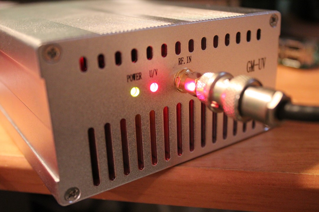
During transmission, the red U / V LED flashes at the fast time stamping of the DMR (Time Slot) mode.
High Input Power
An additional test is made with a higher input power to the amplifier (H position of the RT3 / MD380): Signal received by the repeater with the amplifier in standby is -97 dBm


When the amplifier is switched on, the level received by the repeater when driven by the RT3 / MD380’s in high power level, is equivalent to that received with a low input power: -80 dBm (S9 + 10).

Testing in analogue FM
The test runs show that the amplifier is also operating in FM mode, with an established carrier. The case will certainly heat up twice as fast as a digital traffic “intersected” in time like the DMR or the P25.
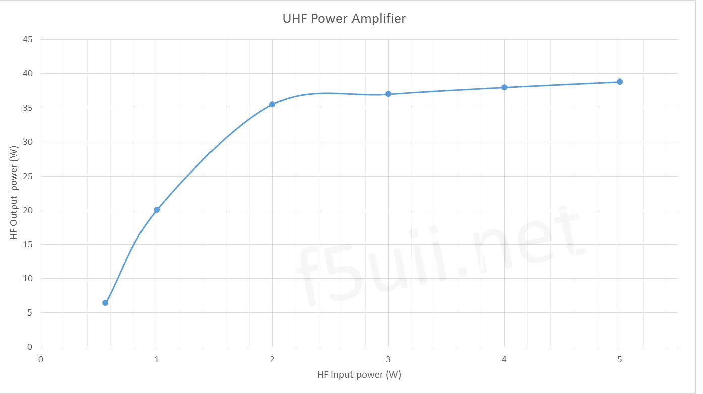
Power appraisal
Here are some operating points of the amplifier.
| U power supply (V) | HF Power input (W) | HF Power output (W) | I power supply (A) | Supply power (W) | Power Efficiency (%) |
|---|---|---|---|---|---|
| 12 | 5 | 27 | 5,34 | 64,1 | 42% |
| 13,8 | 0,56 | 6,4 | 2,16 | 29,8 | 21% |
| 13,8 | 1 | 20 | 3,96 | 54,6 | 37% |
| 13,8 | 2 | 35,5 | 5,91 | 81,6 | 44% |
| 13,8 | 3 | 37 | 6,29 | 86,8 | 43% |
| 13,8 | 4 | 38 | 6,45 | 89,0 | 43% |
| 13,8 | 5 | 38,8 | 6,57 | 90,7 | 43% |
| 14 | 1 | 23,6 | 4,38 | 61,3 | 38% |
| 14 | 5 | 40,5 | 6,78 | 94,9 | 43% |
Characteristics
Standing Wave Ratio
The input SWR of the amplifier is pitiable : it is equal to 3! This means that a quarter of the power is returned by the mismatch of the amplifier to the transmitter.
The consumption
The amplifier consumes less than 50mA when it is in the standby position.
Switching
The amplifier is put active when the input power is applied and reaching 100mW (HF vox).
Spectral analysis
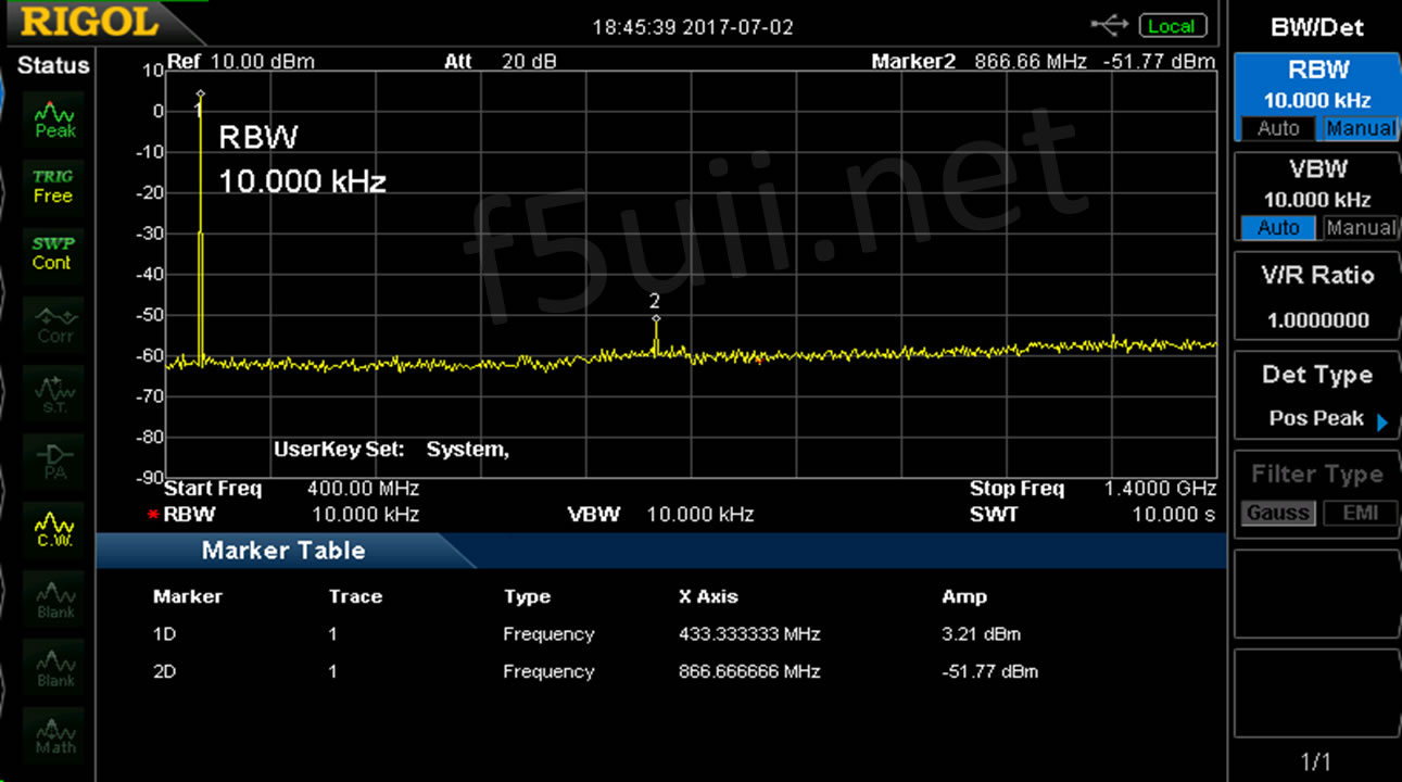
Spectral analysis of the UHF amplifier with Input power at 2 Watts
The presence of a harmonic 2 at -54.98 dBc of the fundamental is noted. No trace of harmonic of higher order.
Appendix 3 of the ITU Radio Regulations which concerns the maximum permissible power levels for spurious emissions (§4 of the Preamble of Decision 12-1241) defines this level in relation to the power of the fundamental emission (dBc): it must not exceed 43 dB + 10 log (P) where P is the power of the transmitter and where 10 log (P) is the power of the transmitter expressed in dBW
In our case, this means that for the 35.5 Watts output, we have a regulatory limit of 58.5 dBc. So we are missing 3.5 dB attenuation. A low pass is therefore necessary to comply with the RR.
Thanks
Thanks to Jean-Pierre, F5AHO for the power measurements and spectral analysis of the amplifier.