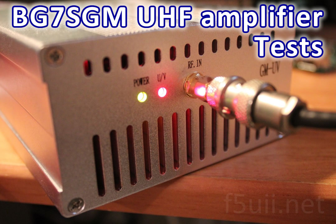
I just bought a UHF amplifier from China. Here is a brief report of its characteristics.
The order
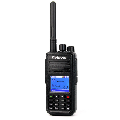
Available on the historic online auction website, I chose to buy this 50-watt UHF amplifier to improve the transmission of my mobile station, for the time being equipped with a 5 Watts MD380 (or RETEVIS RT3) maximum. Curiously the technical description of the product has nothing to do in my opinion with what the amplifier is. It is also available on other sales sites. It was delivered to me exactly 10 calendar days after its online order. Reception is contracted to the postman.
The package arrived pretty battered. Inside, the case packed in several layers of bubble paper, accompanied by a long 1.25 meter power cord. The figure “48” is written to the felt on the paper bubbles.
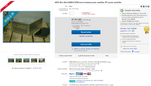
Ebay – 400-470 DMR power amplifier
Connection
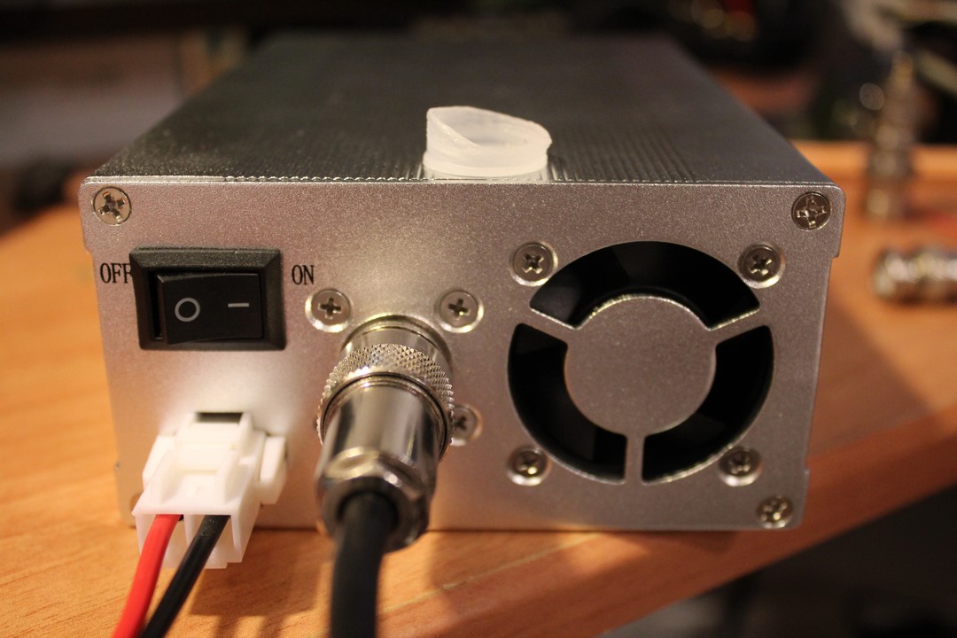
After unpacking, let’s see how the case looks.
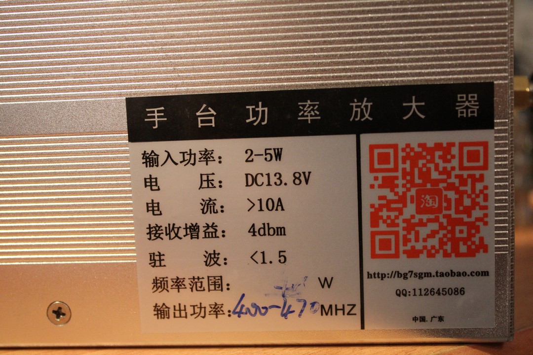
The characteristics label of the amplifier bg7sgm
The first thing we noticed: the side plates carrying the plugs were somewhat distorted. This is certainly due to the fact that the two half-shells are slightly offset to one another. Effect of transport or inaccurate assembly?
The input channel is a female SMA jack. The output is a female PL PLC SO259. I would have preferred to see a N or BNC connector.
I am trying to screw an SMA-BNC adapter into the SMA socket. Surprise: The socket turns a quarter turn … It will be necessary to open the side panel.
The open case
The four screws deposited, I find a fault. The socket is desoldered, it turns around the central pine that remains welded. One leg of the plug is broken. The center female pin is no longer in its proper position in the insulation. The spindle retreated, and the body advanced! It is certain that, as it stands, the contact with the plug will not be made.
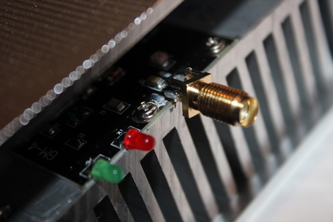
Input RF SMA connector, desoldered and with broken leg
The soldering iron is heated and I correct the problem by successfully pushing the center female pin in its insulation. The whole is re-soldered on the PCB. The box being open, is an opportunity to show you its contents.
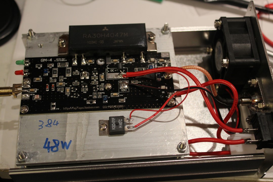
50-watt amplification with MITSUBISHI RA30H4047M
The amplifier contains a Mitsubishi RA30H4047M amplifier module operating in the range 400 to 470 MHz. Here is the RA30H4047M MITSUBISHI datasheet. There is a handwritten “48W” for the power measured at the factory ?
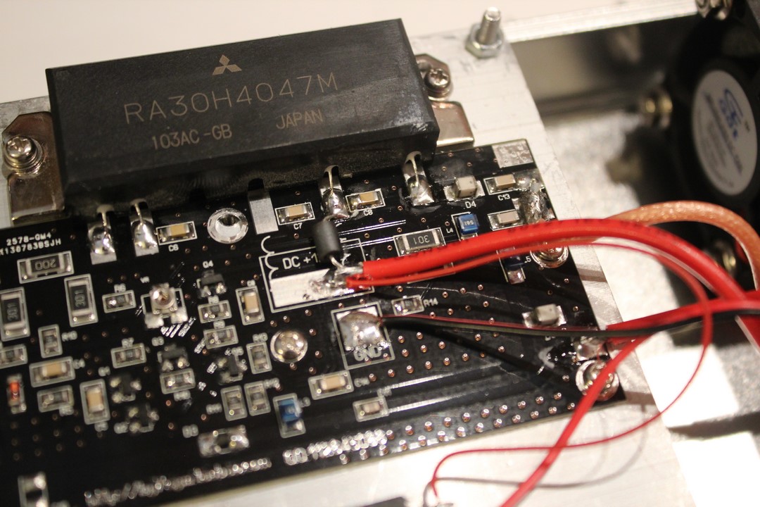
The module is fixed on a large radiator integrated in the case. A thermostat mounted on the radiator operates to activate the blower when the temperature exceeds 40 ° C.
Amplifier Tests
Let us see the behavior of the amplifier working in real situation. I add banana plugs to the power cord. I connect my transmitter DMR (Retevis RT3, equivalent MD380) on one side and the external antenna on the other (remove the protective cap Hi …).
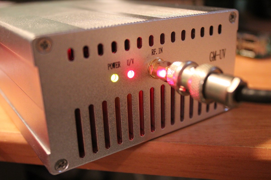
Input side of the UHF amplifier, equipped with an SMA socket.
The antenna is connected at the output of the UHF amplifier
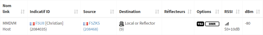
I test directly on the local DMR repeater (F5ZKS).
Low input power
The amplifier is switched off, with low power output (1W). The signal received by the repeater is -106 dBm (S6)
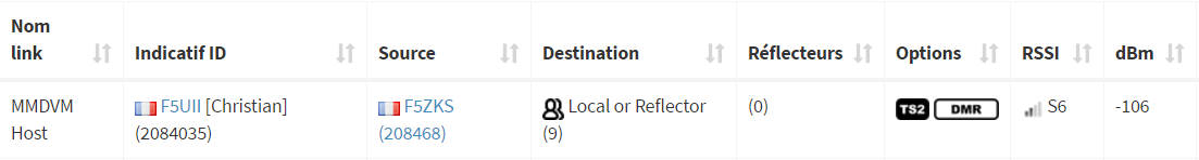
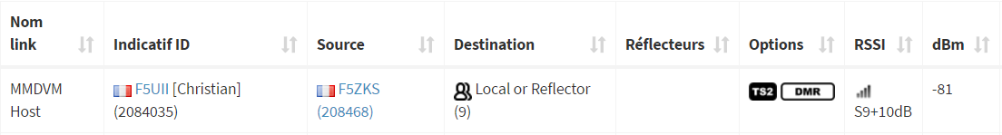
The amplifier is on, the input always being in low power (1W). The signal received by the repeater is -81 dBm (S9 + 10)
During transmission, the red U / V LED flashes at the fast time stamping of the DMR (Time Slot) mode.
High Input Power
An additional test is made with a higher input power to the amplifier (H position of the RT3 / MD380): Signal received by the repeater with the amplifier in standby is -97 dBm
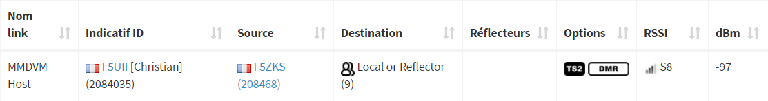
When the amplifier is switched on, the level received by the repeater when driven by the RT3 / MD380’s in high power level, is equivalent to that received with a low input power: -80 dBm (S9 + 10).
Testing in analogue FM
The test runs show that the amplifier is also operating in FM mode, with an established carrier. The case will certainly heat up twice as fast as a digital traffic “intersected” in time like the DMR or the P25.
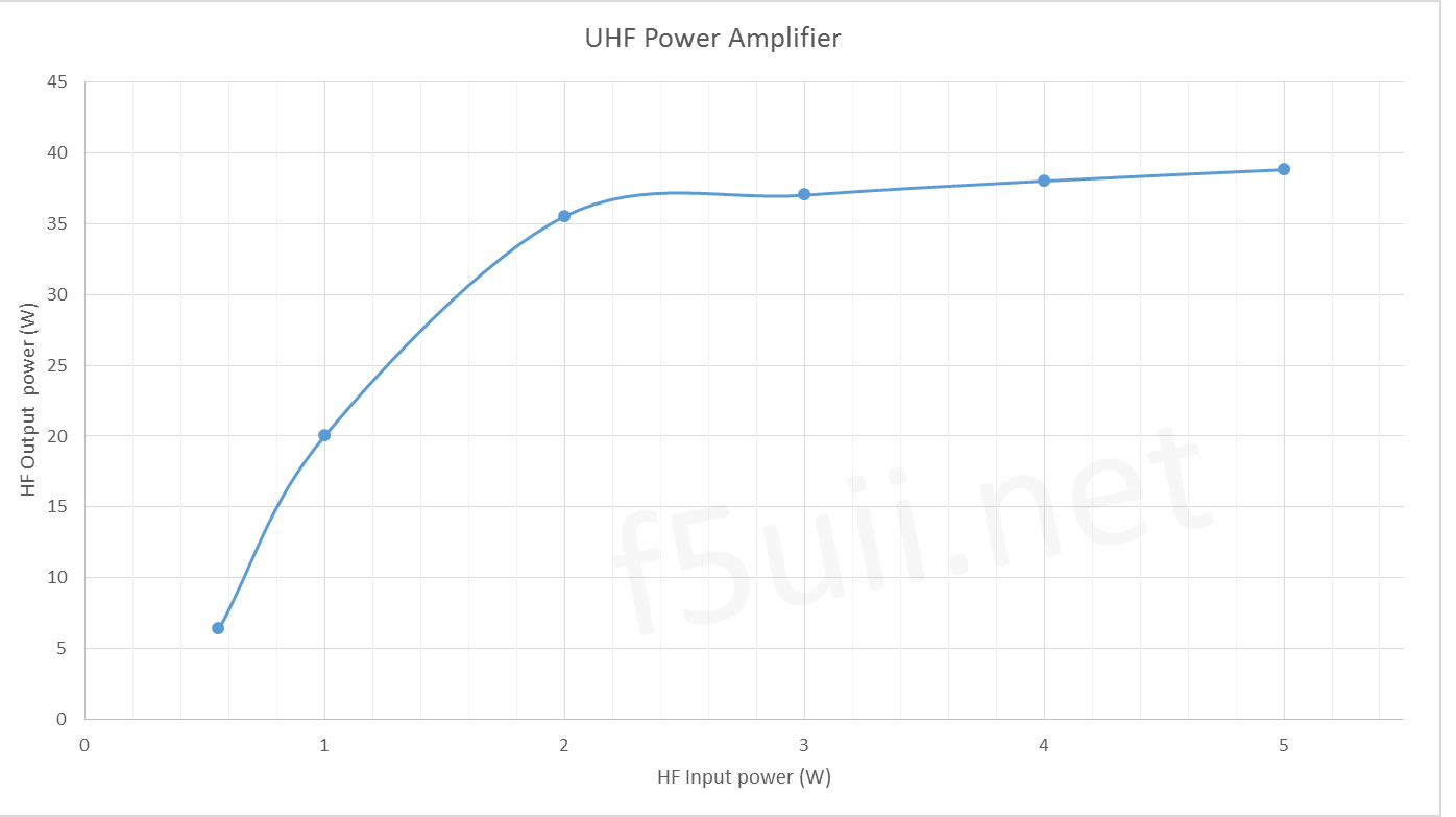
Power appraisal
Here are some operating points of the amplifier.
| U power supply (V) | HF Power input (W) | HF Power output (W) | I power supply (A) | Supply power (W) | Power Efficiency (%) |
|---|---|---|---|---|---|
| 12 | 5 | 27 | 5,34 | 64,1 | 42% |
| 13,8 | 0,56 | 6,4 | 2,16 | 29,8 | 21% |
| 13,8 | 1 | 20 | 3,96 | 54,6 | 37% |
| 13,8 | 2 | 35,5 | 5,91 | 81,6 | 44% |
| 13,8 | 3 | 37 | 6,29 | 86,8 | 43% |
| 13,8 | 4 | 38 | 6,45 | 89,0 | 43% |
| 13,8 | 5 | 38,8 | 6,57 | 90,7 | 43% |
| 14 | 1 | 23,6 | 4,38 | 61,3 | 38% |
| 14 | 5 | 40,5 | 6,78 | 94,9 | 43% |
Characteristics
Standing Wave Ratio
The input SWR of the amplifier is pitiable : it is equal to 3! This means that a quarter of the power is returned by the mismatch of the amplifier to the transmitter.
The consumption
The amplifier consumes less than 50mA when it is in the standby position.
Switching
The amplifier is put active when the input power is applied and reaching 100mW (HF vox).
Spectral analysis
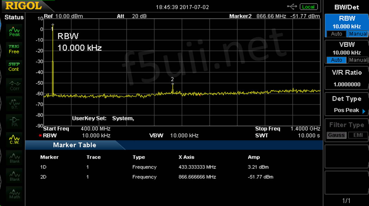
Spectral analysis of the UHF amplifier with Input power at 2 Watts
The presence of a harmonic 2 at -54.98 dBc of the fundamental is noted. No trace of harmonic of higher order.
Appendix 3 of the ITU Radio Regulations which concerns the maximum permissible power levels for spurious emissions (§4 of the Preamble of Decision 12-1241) defines this level in relation to the power of the fundamental emission (dBc): it must not exceed 43 dB + 10 log (P) where P is the power of the transmitter and where 10 log (P) is the power of the transmitter expressed in dBW
In our case, this means that for the 35.5 Watts output, we have a regulatory limit of 58.5 dBc. So we are missing 3.5 dB attenuation. A low pass is therefore necessary to comply with the RR.
Thanks
Thanks to Jean-Pierre, F5AHO for the power measurements and spectral analysis of the amplifier.
73 quel est le prix?
(Translation)
73 what is the price?
Guapo,
Je ne suis pas revendeur, vous trouverez facilement le prix sur les boutiques habituelles (ebay.com, aliexpress.com , …)
(Translation)
Guapo,
I am not a reseller, you will easily find the price on the usual shops (ebay.com, aliexpress.com , …)
73
Bonjour. Merci pour partager ces constatations et mesures.
S’il fonctionne avec un RETEVIS RT3 je suppose qu’il est donc bien compatible TIER 2.
Est ce que vous avez une idée s’il est protégé contre les ROS excessifs, s’il y a un baisse de puissance introduite dans ces cas là etc.?
Utilisé en voiture, il faut s’attendre à des SWR tellement variables…
(Translation)
Hello. Thank you for sharing these findings and measures.
If it works with a RETEVIS RT3 I guess it is therefore TIER 2 compatible.
Do you have any idea if it is protected against excessive SWR, if there is a power drop introduced in these cases etc.?
Used in cars, you can expect SWRs that vary so much…
Bonjour,
Oui, il est tout à fait compatible TIER2. Mon équipement est en voiture depuis plusieurs mois et n’a pas à priori subi d’altération de fonctionnement.
La Datasheet de l’amplificateur Motorola RA30H4047M précise bien la tolérance au ROS élevé.
Load VSWR Tolerance : VDD=15.2V, Pin=50mW, Pout=30W (VGG control), Load VSWR=20:1(Translation)
Good morning. Hello,
Yes, it is fully Tier 2 compatible. My equipment is in my car for several months and has not undergone any deterioration of functioning.
The Motorola RA30H404747M Amplifier Datasheet specifies high SWR tolerance.
Load VSWR Tolerance: VDD=15.2V, Pin=50mW, Pout=30W (VGG control), Load VSWR=20:1Merci bien pour ces précisions. J’ai oublié de préciser que c’était pour un fonctionnement vers des relais DMR. Je me pose les questions sur les temps de commutation, est-ce que ça ne détériore pas la forme d’onde, est-ce que le relais DMR s’en accommode sans problème ?
(Translation)
Thank you very much for that clarification. I forgot to mention that it was for DMR operation. I’m wondering about switching times, does this not damage the waveform, does the DMR repeater accept it without any problems?
Aucun soucis pour fonctionner en DMR, tel que cela est montré dans l’article, il est utilisé sur les relais DMR tier 2.
(Translation)
No worries about DMR operation, as demonstrated in the article, it is used on DMR Tier 2 repeaters.
Merci beaucoup pour votre patience. Je vais être un peu lourd, ne m’en veuillez pas, mais je comprends bien qu’on peut trafiquer en mobile via relais DMR (En première lecture je me suis demandé si vous vouliez dire que cet ampli entrait dans la composition d’un relais…)
Sinon encore une fois merci de mettre à disposition cet article avec ces nombreuses observations et mesures qu’à titre personnel je trouve très utiles. ça répond bien aux questions qu’on peut se poser. Et on ne trouve quasiment pas de littérature sur le sujet
(Translation)
Thank you very much for your patience. I’m going to be a little cumbersome, please don’t blame me, but I fully understand that we can use DMR repeater for mobile phones (I was wondering if you wanted to say that this amplifier was part of the composition of a repeater…)
Otherwise, once again, thank you for providing this article with the many remarks and measures that I personally find very useful. that answers the questions we can ask ourselves. And there is barely any literature on the subject.
AB0LR, I decided to go with the 80 watts amp, because I would like to use it with my open spot. But the open spot will not key the amp.
Any suggestions?
(Traduction)
AB0LR, j’ai décidé d’utiliser l’ampli de 80 watts, car je voudrais l’utiliser avec mon OpenSpot. Mais l’OpenSpot ne fera pas commuter l’ampli.
Des suggestions?
bonjour . le commutation de tx et rx avec de diode ???? . merci pour votre reponse 73 hb3yyr
(Translation)
hello. tx and rx switching with diode?? . Thank you for your reply 73 hb3yyr
Roberto
Oui à priori car aucun bruit de commutation mécanique. L’amplificateur reste silencieux.
Yes, because there is no mechanical switching noise. The amplifier remains silent.
73
What is the output power, with 10mW input?
Can it be used for DMR/D-STAR and other digital modes operation?
(Traduction)
Quelle est la puissance de sortie, avec une entrée de 10mW ?
Peut-on l’utiliser pour les modes DMR/D-STAR et autres modes numériques ?
Stefano,
Given the graph that starts at Pin 560mW, I don’t think we can get an interesting output level with an input power of 10mW ! Yes this amplifier will work for all all digital and even FM modes.
(Traduction)
Vu la courbe qui débute avec Pin de 560mW, je ne pense pas que le puisse le faire fonctionner avec une puissance d’entrée de 10mW !
Oui c’est ampli fonctionnera pour tous les modes numériques et même FM
Ok.
Thanks a lot for the answer.
73’s
(Traduction)
Ok?
Merci beaucoup pour la réponse.
73’s
Attention en effet à cet ampli, en version 50 ou 80w, il ne commute pas de TX à RX, il ne sert qu’en émission et coupe completement la réception.
Il faut pour avoir un fonctionnement normal prévoir l’installation d’un relais coaxial de type cx120a par exemple et etre un peu bricoleur sinon cet ampli ne vous servira a rien.
De mon coté, il était prévu pour une utilisation en relais UHF donc pas de souci de ce coté, mais de nombreuses personnes n’ont pas compris ça et “se font avoir”.
Pensez y! 🙂
(Translation)
Be careful with this amp, in 50 or 80w version, it does not switch from TX to RX, it is only used for transmission and completely cuts reception.
It is necessary to have a normal operation to foresee the installation of a coaxial switch like cx120a for example and to be a little handyman otherwise this amp will not be useful to you has nothing.
On my side, it was intended for UHF repeater use so no problem on that side, but many people didn’t understand that and are “get screwed”.
Think about it! 🙂
Je ne constate absolument pas ce phénomène sur l’équipement testé dans cet article. La réception n’est aucunement altérée, ni en FM, ni en DMR Tier 2.
(Translation)
I do not notice this phenomenon on the equipment tested in this article. Reception is not affected at all, neither in FM, nor in DMR Tier 2.
Bonjour a vous
pour ce genre d’ampli il lui faudra etre un bon RA
donc si il ne commute pas pour la reception il lui faut 2 relais de tres bonne qualité
d’une realisation d’un vox HF simple a faire sur circuit M board a bande
et normalement si cela est bien fait sa roule
Amicalement
Bernard
(Translation)
Hello to you
For this kind of amp it will need to be a good AR
so if it doesn’t switch for reception it needs 2 very good quality relays
I’m sure you’ll be able to get the best out of it, but I’m not sure if it’s a good idea to have a vox HF.
and normally if it is well done it works
Friendly
Bernard
salut
j'ai trouvé votre test sur un amplificateur DMR impecable , et j'ai en main un RA30H4047M
et je veux poser une question :
sur le datasheet l'entré et 50mw en moyenne.
mais dans le test vous avez utilisé meme 5W energie RF
j'ai un RA30H4047M est je lui donne 50mw mais j'ai rien comme output en terme de signal RF
pouvez vous m'éclaircir si je peut augmenter l'energie d'entré ?
Merci
(Traduction)
hello
I found your excellant review on an DMR amplifier, and I have in hand a RA30H4047M and I want to ask a question:
on the datasheet the input is 50mw as an average. but in the test you used even 5W of RF power level.
I have a RA30H4047M and I input 50mw but I have norf signal at output;
Can you clarify if I can increase the input power?
Thank you
Bonjour,
Oui, le circuit seul doit être attaqué à 100mW (20dBm) maximum d'après la datasheet. La platine décrite ici doit être équipé d'un atténuateur en amont pour être utilisable avec les équipements habituels sortant 5W.
Bon dépannage
(Translation)
Yes, the circuit itself must be driven at 100mW (20dBm) maximum according to the datasheet. The board described here must be equipped with an in-line attenuator to be used with the usual 5W output equipment.
Good troubleshooting
Hello and thanks for the review, did you test the Amplifier in Fusion, P25 & NXDN modes.
Thanks
Peter G6VBJ/KM4JXP
(Translation)
Bonjour et merci pour la présentation, avez-vous testé l’amplificateur en mode Fusion, P25 et NXDN.
Remerciements
Peter G6VBJ/KM4JXP
Peter,
I do not test the Amp with other digital mode. Knowing the structure of the various modes, the most constraining is DMR and its split of HF transmissions due to timeslots. Even if I am not an expert in other modes, nothing in my opinion should hinder its use with these modes or even in FM.
Regards, Chris
(Tranduction)
Peter,
Connaissant la constitution des différents modes, le plus contraignant est le DMR et son découpage de transmissions HF du fait des timeslots. Même si je ne suis pas un spécialiste des autres modes, rien à mon sens ne doit gêner à ce qu’il soit utilisé dans ces modes voire en FM.
Salutations, Christian
I just purchased the 80W version on 70cm Band (GM-5 Board) and noted it attenuates the receive signal by some 20+db.
Normally I can hear good signal the Anytone D878 at 0.2uV but via the Amp I have to crank it up to 25uV
I see the Rx Path and diode switching is similar to your GM-3R Board photo and I checked the Diode D3 is forward biased on Rx and reverse biased on Tx so thats all good.
Maybe you have a strong repeater signal in your tests and didnt notice its Deaf…or maybe mine has a wrong capacitor fitted
Please test yours with a Signal Gen into the Ant Socket of the Amp (Disable Tx on the handheld for the channel being used for safety in not frying the Generator if PTT accidently pressed (I used 433MHz Rx).
Specs quoted on ebay for my unit is just 1db +/-0.4 db loss on Rx. I don’t see/measure anything like this.
Unfortunately I don’t have a schematic Diag or a listing the capacitor values as none are visible on the SMD caps.
I do note that yours andmine show a capacitor to 0V far right at bottom which could be shunting all the Rx signal. Interestingly it is marked D5 like for a diode.
(Traduction)
Je viens d’acheter la version 80W sur bande 70cm (carte GM-5) et j’ai remarqué qu’elle atténue le signal de réception d’environ 20+db.
Normalement, j’entends bien le signal de l’Anytone D878 à 0.2uV mais via l’ampli je dois le faire tourner jusqu’à 25uV.
Je vois que le chemin Rx et la commutation des diodes sont similaires à la photo de votre carte GM-3R et j’ai vérifié que la diode D3 est polarisée vers l’avant sur Rx et vers l’arrière sur Tx, ce qui est très bien.
Peut-être que vous avez un signal répéteur fort dans vos tests et que vous n’avez pas remarqué sa surdité… ou peut-être que le mien a un mauvais condensateur…
Veuillez tester le vôtre avec un générateur de signal dans la prise Ant de l’amplificateur (Désactivez Tx sur l’ordinateur de poche pour le canal utilisé pour la sécurité en ne faisant pas frire le générateur si PTT accidentellement appuyé (j’ai utilisé 433MHz Rx).
Les spécifications cotées sur ebay pour mon appareil ne sont que de 1db +/-0,4 db de perte sur Rx. Je ne vois rien de tel.
Malheureusement, je n’ai pas de diagramme schématique ou de liste des valeurs des condensateurs car aucun n’est visible sur les capuchons CMS.
Je note que le vôtre et le mien montrent un condensateur à 0V tout en bas à droite qui pourrait être en train de shunter tout le signal Rx. Il est intéressant de noter qu’il est marqué D5 comme pour une diode.
Bonjour cher OM
pour D5 c’est bien une diode
la D3 est aussi une diode pin genre BA 243 ou 244 il faut regarder la data de ces diode il y en a une avec 0,5 ohms et l’autre avec 1 ohms prende la plus faible valeur car je ne me rappel plus celle que j’ai mise
en sortie il est imperatif de mettre un filtre passe bas sinon dur dur l’enbrouille
Amicalement Bernard
(Translation)
Hello dear OM
for D5 it is indeed a diode
the D3 is also a pin diode like BA 243 or 244 it is necessary to look at the data of these diode there is one with 0,5 ohms and the other with 1 ohms take the weakest value because I do not remember which one I put
In output it is imperative to put a low-pass filter otherwise hard hard confusion
Friendly,
Bernard
Bonsoir, Je serai intéressé pour avoir la méthode de mise en œuvre de l’analyse spectrale (quel type d’attenuateur , quel analyseur de spectre) et la puissance toléré par l’analyseur, car en sortie d’ampli elevée.
73 et merci par avance 😊
(Translation)
Good evening, I will be interested to have the method of implementation of the spectral analysis (which type of attenuator, which spectrum analyzer) and the power tolerated by the analyzer, because at high amplifier output.
73 and thank you in advance 😊
Bonjour,
Vous avez raison, il est très important d’atténuer le signal d’entrée de l’analyseur sous le maximum de puissance admissible par celui-ci. Sinon, l’effet est évidemment la panne irréversible de l’analyseur. Dans le cas de cet article, il s’agit d’un RIGOL DS815 (0 à 1,5GHz). Le maximum acceptable est de +20 dBm (100mW).
Si l’amplificateur sort 50W, le niveau est donc de 47 dBm. Pour arriver à 20 dBm, il faut donc insérer entre l’ampli et l’analyseur un atténuateur d’au moins 27 dBm capable de dissiper 50W. L’atténuateur doit avoir bien-sûr des caractéristiques d’impédance de 50 ohms aux fréquences mesurées (lien Aliexpress).
Il est également possible de réaliser une analyse de spectre d’un signal pour visualiser les niveaux relatifs de fréquences fondamentales et harmoniques sans brancher en direct l’ampli, mais en utilisant une antenne de réception.
(Translation)
Hello,
You are right, it is very important to attenuate the input signal of the analyzer below the maximum power allowed by the analyzer. Otherwise, the effect is obviously the irreversible failure of the analyzer. In the case of this article, it is a RIGOL DS815 (0 to 1.5GHz). The maximum acceptable is +20 dBm (100mW).
If the amplifier outputs 50W, the level is therefore 47 dBm. To reach 20 dBm, it is thus necessary to insert between the amplifier and the analyzer an attenuator of at least 27 dBm capable of dissipating 50W. The attenuator must of course have impedance characteristics of 50 ohms at the frequencies measured (Aliexpress link).
It is also possible to perform spectrum analysis of a signal to display the relative levels of fundamental and harmonic frequencies without connecting the amplifier live, but using a receiving antenna.
Bonjour a tous
j’ai achete chez aliexpresse deux ampli 1 en VHF l’autre en UHF en 40 W
13V8 donc le max
sur le circuit RF Ra30 H 4017 donc d’apres mitsubi A 135 MHZ il sortira 35 W alors comment sortire 40 W a 145 MHZ absurde il est capable d’aller a 170 MHZ mais la pas question de sortire + de 30 ou + W lorsque j’ai essayer il ne sortait que 26 W HUM pas bon du tout
1°) tres tres deçu de ces ampli les prises SO234 socle elle ne sont pas au pas europeen donc
a changer d’office par une prise N chassis
2°) coter UHF Même bazard la prise chassis changer par une N
cote puissance la pareil il ne sort que 24 W sous 13V8 materiel neuf ??? toujour pour 40 sur le carton donc
2 semaine plus tard 3 panne la diode D3 qui se nome A8 la ??? pas de schema donc demerde-toi donc BA 243 mis en place et sa fonctionne
apres la diode du pied du vox celle a la masse HS donc 1n4148 c’est reparti mais j’suis pas content du matos de cher aliexpresse d’ou ils mon pris pour un rigilot sauf que je suis aussi de la partie donc ils sans foutes
donc je suis parti cher mischubi pour avoir deux ci RF de 50 W VHF UHF et avec mes circuits imprimes cela fonctionne mieux que leurs ampli; imperatif filtre passe-bas en sorti pour le VHF de même pour le UHF voila le pris des ci un peux plus chere mais j’ai se que je veux
amicalement Bernard
(Translation)
Hello to all
I bought two amps from aliexpresse, one VHF and one UHF in 40W
13V8 so the max
I’m not sure if it’s a good idea to use the RF Ra30 H 4017 circuit, so according to Mitsubi at 135 MHZ it will output 35 W, so how can it output 40 W at 145 MHZ, which is absurd. It is capable of going to 170 MHZ, but there is no question of outputting more than 30 or more W when I tried it, it was only outputting 26 W, so it’s not good at all
1°) very very disappointed with these amps the SO234 socket they are not at the european step so
to change of course by a N socket – chassis
2°) UHF side Same mess the socket chassis change by one N
power side the same, only 24W under 13V8 new material ??? still for 40 on the box so
2 weeks later 3 breakdowns the diode D3 which is called A8 there ??? no diagram so get lost so BA 243 put in place and it works
then the diode at the base of the vox is out of order so 1n4148 it’s back on but I’m not happy with the equipment from dear aliexpress so they took me for a joke except that I’m also part of the game so they’re not bothered
so I left dear mischubi to have two RF 50 W VHF UHF and with my printed circuits that works better than their amp; imperative low pass filter out for the VHF same for the UHF here is the taken of these a little more expensive but I have what I want
friendly Bernard
Bonjour, j’ai acheté sur Aliexpress la version actuelle de 80 watts équipée d’une carte GM5. L’atténuation de passage sur une branche de réception est d’environ 4 dB. Comme j’ai beaucoup de câbles entre l’émetteur-récepteur et l’amplificateur de puissance, j’aimerais ajouter un préamplificateur. Quelqu’un aurait-il une idée de l’endroit où il serait préférable de l’intégrer ? Existe-t-il des schémas de câblage et un plan de montage ? Meilleures salutations depuis le nord de l’Allemagne. Patzi
Hello, I purchased the current 80-watt version with the GM5 board on AliExpress. The forward attenuation on the receive path is approximately 4 dB. Since I have a lot of cable between the TRX and the PA, I’d like to add a preamplifier. Does anyone have any ideas on where the best place to insert it would be? Are there any schematics or a layout available? Best regards from Northern Germany. Patzi
Guten Tag, ich habe die aktuelle 80 Watt Version mit GM5 Board bei Aliexpress erworben. Die Durgangsdämpfung ein Empfangszweig liegt bei ca. 4 dB. Da ich viel Kabel zwischen TRX und PA habe, würde ich noch einen Vorverstärker einschleifen. Hat jemand eine Idee wo dieser am besten einzuschleifen ist. Gibt es Schaltbilder und ein Layout? Beste Grüße aus Norddeutschland. Patzi