
Intro
After my article about MMDVM and all the installation steps of the MMDVM firmware on the Arduino Due card, here is the article that allows you to answer the questions “how to install MMDVMHost on my Raspberry Pi” and “How do I make MMDVM tunings ?”.
For non-beginners who already master the installation steps of the Raspberry Pi and the MMDVM software, they can directly read the parts devoted to the settings. This article is organized in multiple pages, I invite you to use the summary.

Synoptic of Digital Repeater using MultiMode Digital Voice Modem (MMDVM)
Install the Raspberry Pi Operating System
We will install the latest version of Raspbian Jessie Lite. The “Lite” version is sufficient since we do not need the graphical interface. The file to download is less voluminous than the full version.
Prefer a fast class 10 microSD card.
Download Raspbian
Go to the download page of raspberrypi.org and choose the light version (the version “lite”). Currently, the version available is the Jessie version.
Install the file
The downloaded file is a compressed file (zip), which you will first decompress it. You need to insert your blank microSD card, with an SD adapter into the card reader of your PC. You will use the “burn” Win32ImageWriter software. CAUTION, select the correct drive letter. In case of error, you may destroy the contents of your hard disk !

Once your card is burned, insert your SD (microSD) into the Raspberry Pi port. Connect an Ethernet cable to your network router, and turn on the Raspberry Pi by connecting a power supply to a micro-USB (phone power charger). Make sure your power supply is at least 1 ampere. Indeed some power supplies too weak, allow the lighting of the Raspberry Pi LEDs suggesting that it works, but block in fact its startup.

Connection to the Raspberry Pi
You have connected your Raspberry Pi to your Ethernet network. An automatic IP address was certainly given to him by the router (Internet box) of your network. Determine the IP address of the Raspberry Pi,
-
either by looking at the list of ip addresses connected to your router (or Internet box),
-
either by using a scanning software on your Ethernet network (example Advanced IP Scanner)
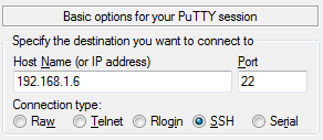
Connect with a terminal software, for example Putty indicating the IP address of the Raspberry Pi, SSH protocol (port 22).

Enter the login and password by default.
login : pi
password : raspberry
Then run the command, to set the Raspberry Pi
raspi-config
Then choose the menu Expand Filesystem to use all available space on your SD card.
Update the operating system with the following commands. The update files are downloaded directly from the internet. The process can be long, and depends on your download speed.
sudo apt update
sudo apt upgrade -y
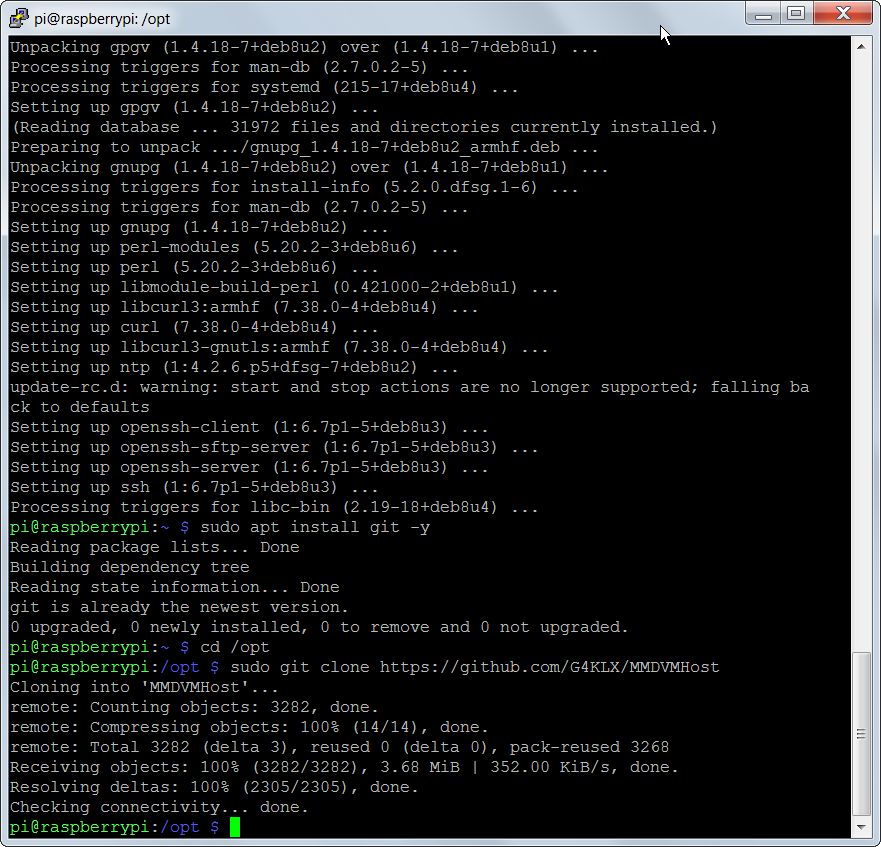
Install the Git software which allows to download directly the projects available on the GitHub Platform.
sudo apt install git -y
A few steps for the Raspberry Pi 3
If you are using a Raspberry Pi 3, here are some modifications to do. This paragraph should not be applied if you have an earlier version (2, B +), go directly to the next paragraph “Download the MMDVMHost software”
- Open the file /boot/cmdline.txt :
- Delete “ttyAMA0” in the line
- Delete the part “console=serial0,115200” in the line
You should have a line like this
dwc_otg.lpm_enable=0 console=tty1 root=/dev/mmcblk0p2 rootfstype=ext4 elevator=deadline fsck.repair=yes rootwait
2. Open now the file /boot/config.txt
sudo nano /boot/config.txt
and add in last line (disables the bluetooth wireless function of Raspberry Pi 3)
dtoverlay=pi3-disable-bt
Download the MMDVMHost software
Change to the directory /opt
cd /opt
We are now downloading the MMDVMHost project from Jonathan, and made available to https://github.com/G4KLX/, with this command:
sudo git clone https://github.com/G4KLX/MMDVMHost

Compile the MMDVMHost software
We change now to the /opt/MMDVMHost directory that contains the source code previously downloaded. We will launch the compilation of the software.
cd /opt/MMDVMHost/
sudo make
pi@raspberrypi:/opt/MMDVMHost $ sudo make
g++ -g -O3 -Wall -std=c++0x -pthread -c -o AMBEFEC.o AMBEFEC.cpp
g++ -g -O3 -Wall -std=c++0x -pthread -c -o BPTC19696.o BPTC19696.cpp
g++ -g -O3 -Wall -std=c++0x -pthread -c -o Conf.o Conf.cpp
g++ -g -O3 -Wall -std=c++0x -pthread -c -o CRC.o CRC.cpp
g++ -g -O3 -Wall -std=c++0x -pthread -c -o Display.o Display.cpp
g++ -g -O3 -Wall -std=c++0x -pthread -c -o DMRControl.o DMRControl.cpp
g++ -g -O3 -Wall -std=c++0x -pthread -c -o DMRCSBK.o DMRCSBK.cpp
g++ -g -O3 -Wall -std=c++0x -pthread -c -o DMRData.o DMRData.cpp
g++ -g -O3 -Wall -std=c++0x -pthread -c -o DMRDataHeader.o DMRDataHeader.cpp
g++ -g -O3 -Wall -std=c++0x -pthread -c -o DMREMB.o DMREMB.cpp
g++ -g -O3 -Wall -std=c++0x -pthread -c -o DMREmbeddedLC.o DMREmbeddedLC.cpp
g++ -g -O3 -Wall -std=c++0x -pthread -c -o DMRFullLC.o DMRFullLC.cpp
g++ -g -O3 -Wall -std=c++0x -pthread -c -o DMRIPSC.o DMRIPSC.cpp
g++ -g -O3 -Wall -std=c++0x -pthread -c -o DMRLookup.o DMRLookup.cpp
g++ -g -O3 -Wall -std=c++0x -pthread -c -o DMRLC.o DMRLC.cpp
g++ -g -O3 -Wall -std=c++0x -pthread -c -o DMRShortLC.o DMRShortLC.cpp
g++ -g -O3 -Wall -std=c++0x -pthread -c -o DMRSlot.o DMRSlot.cpp
g++ -g -O3 -Wall -std=c++0x -pthread -c -o DMRSlotType.o DMRSlotType.cpp
g++ -g -O3 -Wall -std=c++0x -pthread -c -o DMRAccessControl.o DMRAccessControl.cpp
g++ -g -O3 -Wall -std=c++0x -pthread -c -o DMRTrellis.o DMRTrellis.cpp
g++ -g -O3 -Wall -std=c++0x -pthread -c -o DStarControl.o DStarControl.cpp
g++ -g -O3 -Wall -std=c++0x -pthread -c -o DStarHeader.o DStarHeader.cpp
g++ -g -O3 -Wall -std=c++0x -pthread -c -o DStarNetwork.o DStarNetwork.cpp
g++ -g -O3 -Wall -std=c++0x -pthread -c -o DStarSlowData.o DStarSlowData.cpp
g++ -g -O3 -Wall -std=c++0x -pthread -c -o Golay2087.o Golay2087.cpp
g++ -g -O3 -Wall -std=c++0x -pthread -c -o Golay24128.o Golay24128.cpp
g++ -g -O3 -Wall -std=c++0x -pthread -c -o Hamming.o Hamming.cpp
g++ -g -O3 -Wall -std=c++0x -pthread -c -o Log.o Log.cpp
g++ -g -O3 -Wall -std=c++0x -pthread -c -o MMDVMHost.o MMDVMHost.cpp
g++ -g -O3 -Wall -std=c++0x -pthread -c -o Modem.o Modem.cpp
g++ -g -O3 -Wall -std=c++0x -pthread -c -o Nextion.o Nextion.cpp
g++ -g -O3 -Wall -std=c++0x -pthread -c -o NullDisplay.o NullDisplay.cpp
g++ -g -O3 -Wall -std=c++0x -pthread -c -o QR1676.o QR1676.cpp
g++ -g -O3 -Wall -std=c++0x -pthread -c -o RS129.o RS129.cpp
g++ -g -O3 -Wall -std=c++0x -pthread -c -o SerialController.o SerialController.cpp
g++ -g -O3 -Wall -std=c++0x -pthread -c -o SHA256.o SHA256.cpp
g++ -g -O3 -Wall -std=c++0x -pthread -c -o StopWatch.o StopWatch.cpp
g++ -g -O3 -Wall -std=c++0x -pthread -c -o Sync.o Sync.cpp
g++ -g -O3 -Wall -std=c++0x -pthread -c -o TFTSerial.o TFTSerial.cpp
g++ -g -O3 -Wall -std=c++0x -pthread -c -o Thread.o Thread.cpp
g++ -g -O3 -Wall -std=c++0x -pthread -c -o Timer.o Timer.cpp
g++ -g -O3 -Wall -std=c++0x -pthread -c -o UDPSocket.o UDPSocket.cpp
g++ -g -O3 -Wall -std=c++0x -pthread -c -o Utils.o Utils.cpp
g++ -g -O3 -Wall -std=c++0x -pthread -c -o YSFControl.o YSFControl.cpp
g++ -g -O3 -Wall -std=c++0x -pthread -c -o YSFConvolution.o YSFConvolution.cpp
g++ -g -O3 -Wall -std=c++0x -pthread -c -o YSFFICH.o YSFFICH.cpp
g++ -g -O3 -Wall -std=c++0x -pthread -c -o YSFNetwork.o YSFNetwork.cpp
g++ -g -O3 -Wall -std=c++0x -pthread -c -o YSFPayload.o YSFPayload.cpp
g++ AMBEFEC.o BPTC19696.o Conf.o CRC.o Display.o DMRControl.o DMRCSBK.o DMRData.o DMRDataHeader.o DMREMB.o DMREmbeddedLC.o DMRFullLC.o DMRIPSC.o DMRLookup.o DMRLC.o DMRShortLC.o DMRSlot.o DMRSlotType.o DMRAccessControl.o DMRTrellis.o DStarControl.o DStarHeader.o DStarNetwork.o DStarSlowData.o Golay2087.o Golay24128.o Hamming.o Log.o MMDVMHost.o Modem.o Nextion.o NullDisplay.o QR1676.o RS129.o SerialController.o SHA256.o StopWatch.o Sync.o TFTSerial.o Thread.o Timer.o UDPSocket.o Utils.o YSFControl.o YSFConvolution.o YSFFICH.o YSFNetwork.o YSFPayload.o -g -O3 -Wall -std=c++0x -pthread -lpthread -o MMDVMHost
pi@raspberrypi:/opt/MMDVMHost $
Configuring MMDVMHost
All configuration of the MMDVM operation is carried out from the MMDVM.ini single configuration file. It is in this file that we will indicate in particular which modes will be activated (DStar, C4FM, DMR, …). In our case, we only set the DMR digital mode en route (Enable = 1 in the [DMR] section)
Also, you will find your repeater callsign, as well as the ID (CCS7) you will surely receive in return of your online registration.
sudo nano /opt/MMDVMHost/MMDVM.ini
[General]
Callsign=F1ZZZ
Timeout=180       # Transmitter timeout in seconds. Default is: 120s
Duplex=1          # Is this station Simplex or Duplex. DVMega is simplex. Default is: 1
# ModeHang=10     # Time to stay in mode after receiption. If set overrides RFModemHang and NetModemHang
RFModeHang=10     # Time to stay in mode after RF-receiption Default is: 10s
NetModeHang=3     # Time to stay in mode after Network-receiption Default is: 3s
Display=None      # If a screen of LCD is on the device (None or name)
Daemon=0          # Run in background

[Info]
RXFrequency=431950000    # Receiver frequency in Hz Used by DVMega, reported to DMR-Master. Default is: 0Hz
TXFrequency=439550000    # Transmitter frequency in Hz. Used by DVMega, reported to DMR-Master. Default is: 0Hz
Power=5                  # Power in Watts, for informational use only. Keep below 99 for BrandMeister
Latitude=47.7            # if set, reported to DMR-Master, causes recognition as repeater in BrandMeister
Longitude=7.4            # if set, reported to DMR-Master, causes recognition as repeater in BrandMeister
Height=12                # if set, reported to DMR-Master, causes recognition as repeater in BrandMeister
Location=Colmar
Description=Multi-Mode Repeater
URL=www.yourwebsite.net

[Log]
# Logging levels, 0=No logging
DisplayLevel=2          # log Debug to console. Default is: 1
FileLevel=2             # log Debug to file. Default is: 1
FilePath=.
FileRoot=MMDVM

[CW Id]
Enable=1                # Enable the CW Id
Time=10                 # How often to ID in minutes

[Modem]
Port=/dev/ttyACM0
# Port=\\.\COM3
TXInvert=0              # Invert TX data. Needed for some transmitters. Default is: 0
RXInvert=0              # Invert RX data. Needed for some receivers. Default is: 0
PTTInvert=0             # PTT goes low to transmit. Invert for some transmitters. Default is: 0
TXDelay=100             # Give the transmitter time to settle in ms. Default is: 100ms
DMRDelay=0              # Compensate for delay in transmitter audio chain in ms . Usually DSP based. Default is: 0.0ms
RXLevel=50              # Soft control for receive level. Not used by DVMega. Default is: 100%
TXLevel=50              # Soft Control for transmit level. Not used by DVMega. Default is: 100%
# D-StarTXLevel=50
# DMRTXLevel=50
# YSFTXLevel=50
OscOffset=0             # Tweak the Due oscillator if not using the TCXO. Default is: 0ppm
RSSIMultiplier=1
RSSIOffset=10
Debug=0

[D-Star]
Enable=0                # Enable D-Star repeater mode. Default is: 1
Module=C
SelfOnly=0              # If set, only own ID can operate. Default is: 0

[DMR]
Enable=1                # Enable DMR repeater mode. Default is: 1
Beacons=1               # Enable transmission of DMR-Beacons, used for DMR-Roaming
Id=2084333              # DMR ID of this station (repeater)
ColorCode=1             # Color Code to use for DMR repeater access. Default is: 2
SelfOnly=0              # If set, only own ID can operate. Default is: 0
# Prefixes=234,235      # These prefixes are whitelisted for operation. Default is: 0
LookupFile=DMRIds.dat
CallHang=3              # Time to answer in same Talk Group. Default is: 3
TXHang=4                # Time that TX stays on transmission after DMR-over. Default is: 3
#Blacklist=
#DstIdBlackListSlot1RF=       # comma separated list TGs to block on RF Slot1
#DstIdBlackListSlot2RF=       # comma separated list TGs to block on RF Slot2
#DstIdWhiteListSlot1RF=       # comma separated list TGs to allow on RF Slot1
#DstIdWhiteListSlot2RF=       # comma separated list TGs to allow on RF Slot2
#DstIdBlackListSlot1NET=      # comma separated list TGs to block on NET Slot1
#DstIdBlackListSlot2NET=      # comma separated list TGs to block on NET Slot2
#DstIdWhiteListSlot1NET=      # comma separated list TGs to allow on NET Slot1
#DstIdWhiteListSlot2NET=      # comma separated list TGs to allow on NET Slot2

[System Fusion]
Enable=0                      # Enable Fusion repeater mode. Default is: 1

[D-Star Network]
Enable=0                      # Enable D-Star network connection. Requires ircDDBGateway. Default is: 1
GatewayAddress=127.0.0.1
GatewayPort=20010             # UDP port ircDDBGateway is listening on.
LocalPort=20011               # UDP port MMDVMHost is listening on.
Debug=0

[DMR Network]
Enable=1                      # Enable DMR network connection. Default is: 1
Address=51.254.100.133
Port=62031                    # Port DMRMaster is listening on
# Local=3350                  # Local UDP port if needed else random
Password=passwOrd             # Access password of DMR Master
RSSI=0                        # Enable RSSI measure. Defaukt is: 0
Slot1=1                       # Enable Slot 1 Do not enable for DVMega. Default is: 1
Slot2=1                       # Enable Slot 2. Default is: 1
Debug=1                       # Default is: 0

[System Fusion Network]
Enable=0                      # Enable Fusion network connection
LocalAddress=127.0.0.1
LocalPort=3200
GwyAddress=127.0.0.1
GwyPort=4200
Debug=0

[TFT Serial]
Port=/dev/ttyAMA0
Brightness=50

[HD44780]
Rows=2
Columns=16

# For basic HD44780 displays (4-bit connection)
# rs, strb, d0, d1, d2, d3
Pins=11,10,0,1,2,3

# Device address for I2C
I2CAddress=0x20

# PWM backlight
PWM=0
PWMPin=21
PWMBright=100
PWMDim=16

DisplayClock=1
UTC=0

[Nextion]
Port=/dev/ttyAMA0
Brightness=50
DisplayClock=1
UTC=0
IdleBrightness=20

[OLED]
Type=3
Brightness=0
Invert=0
First validation test, before calibration
To verify that
- the MMDVMHost software installed on the Raspberry Pi communicates correctly with the MMDVM firmware installed on the Arduino Due,
- the MMDVMHost software properly connects the DMR BrandMeister server

Launch the software directly, indicating the path to the configuration file.
sudo /opt/MMDVMHost/MMDVMHost /opt/MMDVMHost/MMDVM.ini
The arduino starts blinking (slowly then quickly when the repeater is transmitting).

This gives you the following traces, with incoming traffic coming from the network (internet).
I: 2016-08-18 19:29:50.005 This software is for use on amateur radio networks only,
I: 2016-08-18 19:29:50.005 it is to be used for educational purposes only. Its use on
I: 2016-08-18 19:29:50.005 commercial networks is strictly prohibited.
I: 2016-08-18 19:29:50.005 Copyright(C) 2015, 2016 by Jonathan Naylor, G4KLX and others
M: 2016-08-18 19:29:50.005 MMDVMHost-20160816 is starting
I: 2016-08-18 19:29:50.006 General Parameters
I: 2016-08-18 19:29:50.006     Callsign: F1ZZZ
I: 2016-08-18 19:29:50.006     Duplex: yes
I: 2016-08-18 19:29:50.006     Timeout: 180s
I: 2016-08-18 19:29:50.006     RF Mode Hang: 10s
I: 2016-08-18 19:29:50.006     Net Mode Hang: 3s
I: 2016-08-18 19:29:50.006     D-Star: disabled
I: 2016-08-18 19:29:50.006     DMR: enabled
I: 2016-08-18 19:29:50.006     YSF: disabled
I: 2016-08-18 19:29:50.006 Modem Parameters
I: 2016-08-18 19:29:50.006     Port: /dev/ttyACM0
I: 2016-08-18 19:29:50.006     RX Invert: no
I: 2016-08-18 19:29:50.006     TX Invert: yes
I: 2016-08-18 19:29:50.007     PTT Invert: no
I: 2016-08-18 19:29:50.007     TX Delay: 100ms
I: 2016-08-18 19:29:50.007     DMR Delay: 0 (0.0ms)
I: 2016-08-18 19:29:50.007     RX Level: 50%
I: 2016-08-18 19:29:50.007     D-Star TX Level: 50%
I: 2016-08-18 19:29:50.007     DMR TX Level: 50%
I: 2016-08-18 19:29:50.007     YSF TX Level: 50%
I: 2016-08-18 19:29:50.007     RX Frequency: 431950000Hz
I: 2016-08-18 19:29:50.007     TX Frequency: 439550000Hz
I: 2016-08-18 19:29:50.007     Osc. Offset: 0ppm
M: 2016-08-18 19:29:50.007 Opening the MMDVM
I: 2016-08-18 19:29:52.019 MMDVM protocol version: 1, description: MMDVM 20160624 24                          kHz (D-Star/DMR/System Fusion/CW Id)
I: 2016-08-18 19:29:52.039 Display Parameters
I: 2016-08-18 19:29:52.040     Type: None
I: 2016-08-18 19:29:52.040 DMR Network Parameters
I: 2016-08-18 19:29:52.040     Address: 51.254.100.133
I: 2016-08-18 19:29:52.040     Port: 62031
I: 2016-08-18 19:29:52.040     Local: random
I: 2016-08-18 19:29:52.040     Slot 1: enabled
I: 2016-08-18 19:29:52.040     Slot 2: enabled
I: 2016-08-18 19:29:52.040     RSSI: disabled
I: 2016-08-18 19:29:52.040 Info Parameters
I: 2016-08-18 19:29:52.040     Callsign: F5UII-R
I: 2016-08-18 19:29:52.040     RX Frequency: 431950000Hz
I: 2016-08-18 19:29:52.040     TX Frequency: 439550000Hz
I: 2016-08-18 19:29:52.041     Power: 5W
I: 2016-08-18 19:29:52.041     Latitude: 47.700001deg N
I: 2016-08-18 19:29:52.041     Longitude: 7.400000deg E
I: 2016-08-18 19:29:52.041     Height: 12m
I: 2016-08-18 19:29:52.041     Location: "Colmar"
I: 2016-08-18 19:29:52.041     Description: "Multi-Mode Repeater"
I: 2016-08-18 19:29:52.041     URL: "www.yourwebsite.net"
M: 2016-08-18 19:29:52.041 Opening DMR IPSC
I: 2016-08-18 19:29:52.041 CW Id Parameters
I: 2016-08-18 19:29:52.041     Time: 10 mins
I: 2016-08-18 19:29:52.041 DMR Parameters
I: 2016-08-18 19:29:52.041     Id: 2084333
I: 2016-08-18 19:29:52.041     Color Code: 1
I: 2016-08-18 19:29:52.041     Self Only: no
I: 2016-08-18 19:29:52.042     Prefixes: 0
I: 2016-08-18 19:29:52.042     Lookup File: DMRIds.dat
I: 2016-08-18 19:29:52.042     Call Hang: 3s
I: 2016-08-18 19:29:52.042     TX Hang: 3s
I: 2016-08-18 19:29:52.042     RSSI Multiplier: 1
I: 2016-08-18 19:29:52.042     RSSI Offset: 10
I: 2016-08-18 19:29:52.297 Loaded 40545 DMR Ids to the callsign lookup table
M: 2016-08-18 19:29:52.297 MMDVMHost-20160816 is running
M: 2016-08-18 19:30:02.240 Logged into the master successfully
M: 2016-08-18 19:52:37.767 DMR Slot 1, received network voice header from F1RRJ to TG 208
M: 2016-08-18 19:52:48.764 DMR Slot 1, received network end of voice transmission, 10.7 seconds, 0% packet loss, BER: 0.0%
M: 2016-08-18 19:55:40.749 DMR Slot 1, received network voice header from F1RRJ to TG 208
M: 2016-08-18 19:55:57.644 DMR Slot 1, received network end of voice transmission, 16.8 seconds, 1% packet loss, BER: 0.0%
M: 2016-08-18 19:56:15.277 DMR Slot 1, received network voice header from F4FHM to TG 208
M: 2016-08-18 19:56:15.826 DMR Slot 1, received network end of voice transmission, 0.5 seconds, 0% packet loss, BER: 3.0%
M: 2016-08-18 19:58:49.881 DMR Slot 1, received network voice header from ON7FI to TG 208
M: 2016-08-18 19:58:50.858 DMR Slot 1, received network end of voice transmission, 0.8 seconds, 0% packet loss, BER: 0.0%
M: 2016-08-18 19:59:08.617 DMR Slot 1, received network voice header from ON7FI to TG 208
M: 2016-08-18 19:59:15.952 DMR Slot 1, received network end of voice transmission, 6.8 seconds, 0% packet loss, BER: 0.0%
M: 2016-08-18 19:59:38.423 DMR Slot 1, received network voice header from ON7FI to TG 208
M: 2016-08-18 19:59:47.558 DMR Slot 1, received network end of voice transmission, 9.1 seconds, 0% packet loss, BER: 0.0%
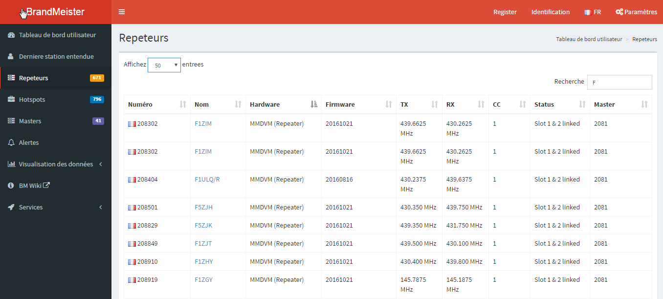
By visiting the Homebrew Repeaters page on the Brandmeister website, you will see the callsign of your repeater appearing.

MMDVM Firmware Command Specifications
For the curious, here are the specifications and commands of the firmware to send to the arduino MMDVM via the serial port : MMDVM Specification 20150922 . Note that this documentation dates from September 2015. The information has been able to evolve since.
Tuning the DMR digital mode
The DMR mode is not the simplest mode to set. Logically, the other modes will also be then adjusted. We will see what method to reach this goal.
We present the technique allowing you to have an optimum result. You will need to equip yourself with:
Nous vous présentons la technique permettant d’avoir un résultat optimum. Vous devrez vous équiper avec :
- A spectrum analyzer and its attenuators
- an oscilloscope
First, we will set the transmission of the repeater, then in a second step, the reception of the repeater. For this, we will use the calibration software MMDVMCal. Let’s see how to install it.
Installing the Calibration Software
Download MMDVMCal
Change to the /opt directory
cd /opt
We are now downloading Jonathan’s MMDVMCal project and made available on https://github.com/G4KLX/, with this command:
cd /opt/
sudo git clone https://github.com/G4KLX/MMDVMCal
Compile the MMDVMCal software
We change now to the /opt/MMDVMCal directory that contains the source code previously downloaded. We will launch the compilation of the software.
cd /opt/MMDVMCal/
sudo make
Tuning the DMR transmission
To make our adjustments, your transceivers must be connected to the MMDVM filter shield. Take a moment to check your wire-to-wire connections before you start the settings (Rx Audio, Squelch, Tx Audio, PTT and Ground).
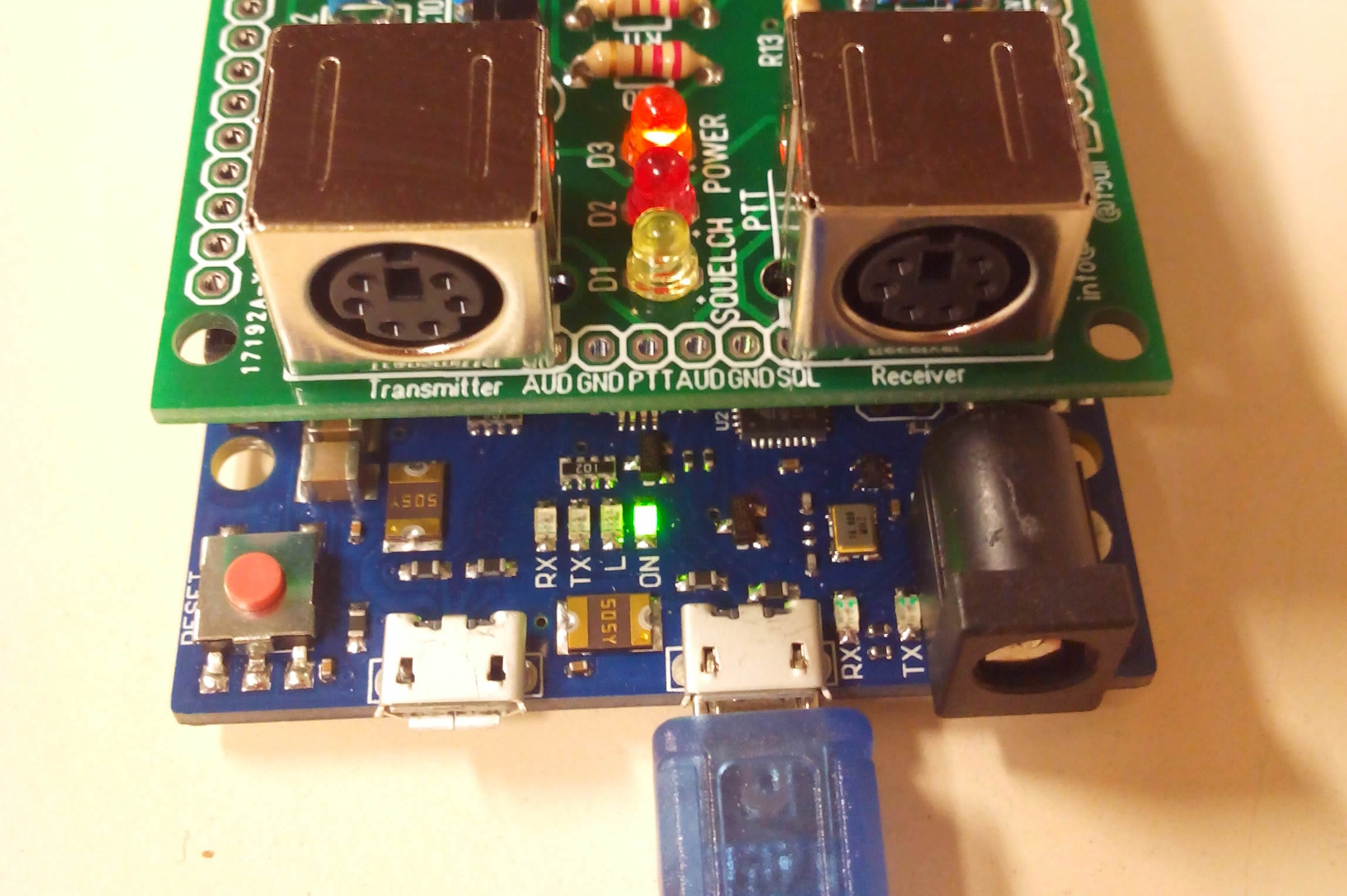
In my case, I use two Motorola GM360 sets. They are connected to the filter shield with PS2 (6-pin) connectors, and on the GM360 accessory socket (Supplier eg Aliexpress). The Squelch (COR) signal level must be checked (active = high level), and if necessary be reversed by programming the GM360.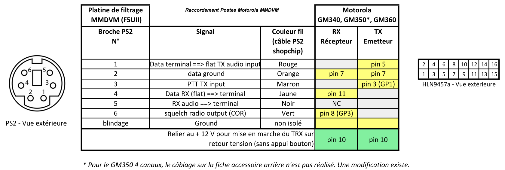


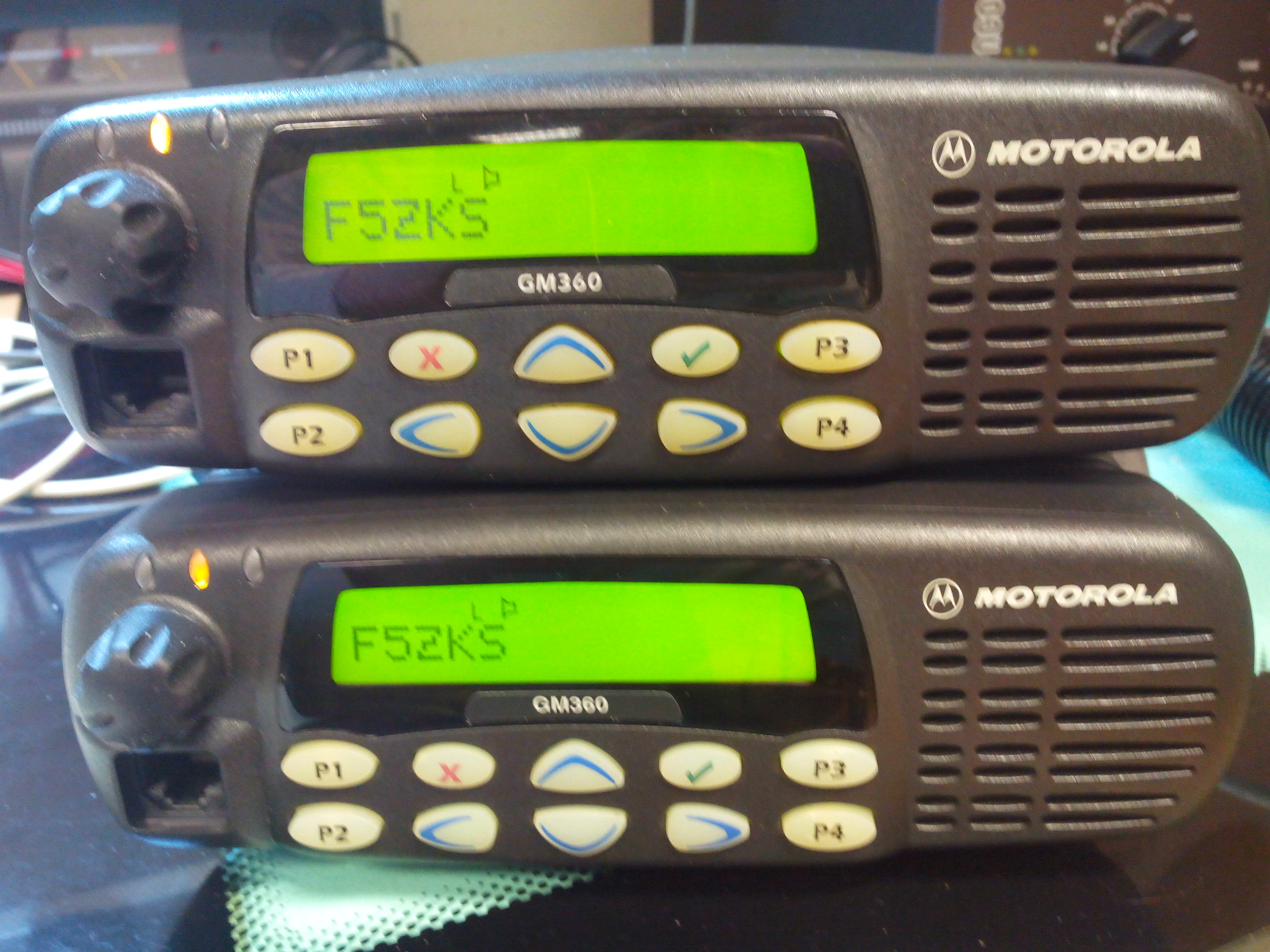
Motorola GM360

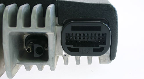
GM360 Rear Accessory Connector

MMDVM, filter shield with PS2 connectors for transceivers
Start the tuning software, specifying the serial port on which the arduino is connected to the Raspberry Pi. Usually, the USB port is created under /dev/ttyACM0
sudo /opt/MMDVMCal/MMDVMCal /dev/ttyACM0
The help menu is displayed (h key).
The commands are:
    H/h      Display help
    I        Toggle transmit inversion
    i        Toggle receive inversion
    P/p      Toggle PTT inversion
    Q/q      Quit
    R        Increase receive level
    r        Decrease receive level
    T        Increase transmit level
    t        Decrease transmit level
    D        DMR Deviation Mode (Adjust for 2.75Khz Deviation)
    d        Return to Dstar Mode
    V/v      Display version of MMDVMCal
    <space>  Toggle transmit
Place the “D” command (shift key D) to enter the DMR mode setting. To switch to transmission, press the space bar. The PTT light on the MMDVM board must light up. Your transmitter must now emit. At this time, the MMDVMCal software sends a low-frequency signal of 1200 Hz to your transmitter. You can optionally listen the signal with an analog receiver set on the output frequency of your (future) relay.


Your spectrum analyzer must now be connected to the RF output of the transmitter. Be sure to set up a sufficiently powerful attenuator to protect your analyzer. Set your analyzer to see the transmit signal.
We will start by reducing the LF signal level generated by the MMDVM board, reducing the gain to 0%. To do this, press the “t” key (lower key t) several times. Check that the multi-turn TX potentiometer (R98 on my shield) is close to the middle of its range, and in any case, not at the end of the range.
Since the LF level is zero, you should only read the fundamental frequency on your analyzer (Bessel function J0).

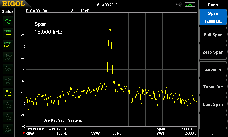
Fundamental frequency with amplitude J0
We will now increase the level of the low frequency 1200 Hz signal, the “harmonics” will appear to the left and right of the line J0. To increase the level, press the “T” key (uppercase T).
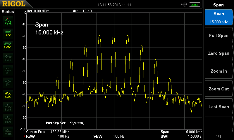
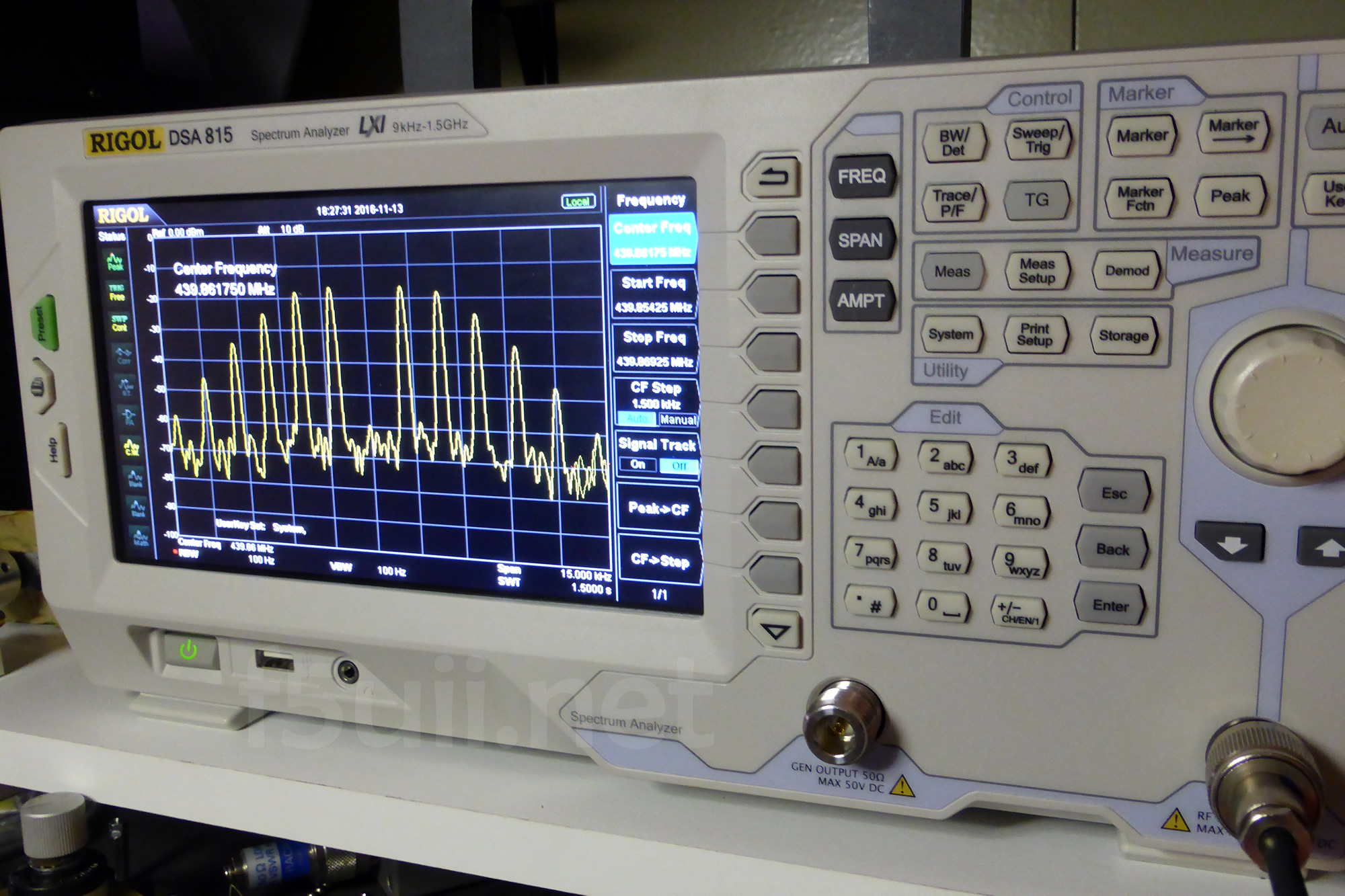
The frequency modulation spectrum with a 1200Hz BF signal (J0, J1, J2, J3 and J4 are present)
Now, by continuing to increase the signal level with the “T” key (shift key T), you will see that the amplitude of the J0 line decreases. Beyond this point, by continuing to press “T”, the amplitude of the line J0 increases again. Note down the percentage you have reached, when the line is at minimum amplitude. We will save this TX level percentage later in the MMDVMHost configuration file.
This operating point can now be fine-tuned to the transmit potentiometer R98 of the filtering MMDVM shield, in order to always look for the amplitude of the lowest J0. This gives a spectrum like that there. Your shield is noww tune to transmit DMR.
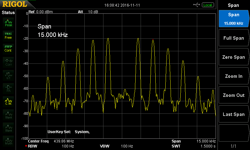
Optimum adjustment of the DMR emission, the line J0 has disappeared

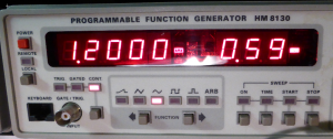
1,2000 kHz and 600 mV Peak-to-peak
The signal injected on the Motorola GM360 corresponding to this operating point has an amplitude of 0.6 V. Note that this level is dependent on your transceiver, and that may not be an universal reference.

Amplitude du signal MMDVMCal pour J0 au minimum (poste GM360)
In DMR, the frequency modulation deviation must be 2.75 kHz. MMDVMCal generates a signal of 1200 Hz. The Bessel J0 appears null when modulation index (x) is equal to 2.4. With this setting where the line J0 disappears, the operating point is set the deviation to 2.88 kHz (index = 2880/1200 = 2.4). We have than to minimize the TX Level (in mmdvm.ini file) by 5% to set the right deviation. For example, if we have find a TXLevel of 85% in MMDVMCal, we will set in mmdvm.ini (85*0.95 =) 81 (Read below).

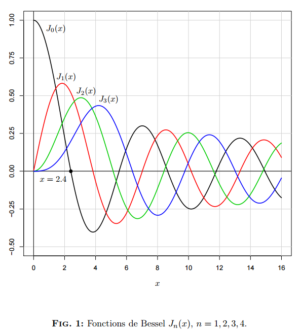
Bessel Functions. Excerpt from Work Practical Electronics,École Polytechnique de l’UNS (in french)
Tuning with a SDR receiver (USB RTL key)


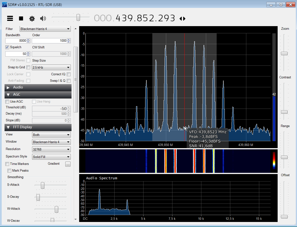
Setting DMR using a simple SDR RTL key
Tuning DMR reception
Let’s see how to set the reception. This second phase is simpler. Indeed, the goal is simply that the audio levels are not too strong and do not saturate the analog input of the arduino Due. We will use an oscilloscope for this operation.
First of all, I specify that your receiving station must output a low frequency signal without preemphasis or de-emphasis. The GM360 signal sent to the accessory jack is “Audio RX Flat”. If you can, configure your radio to send RX audio even if the squelch (COR) is not active.
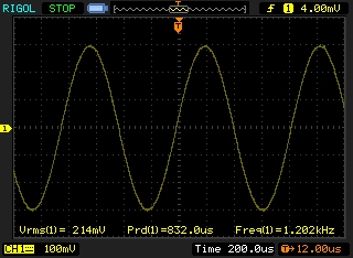
Verification consists in checking the oscilloscope signal A0 which is sent to the arduino. Place your tip on pin 7 of IC2. You can take mass on JP5 or JP6 for example.
Even in the absence of an RF signal by the receiver, the filter amplifies the signals. If signal saturation exceeds 3V peak-to-peak, decrease the amplitude by turning potentiometer R99.
This is an example of signals you have on analog input A0 when a DMR signal is received by the receiver. We can clearly seen that the DMR is a digital mode with “switched frames”, with “no transmission” periods (largest amplitudes), where the noise signals evolve at a maximum of +/- 1 V. The DMR signals evolve at about +/- 400mV
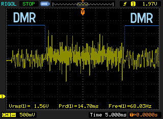
DMR transmission
Saving settings in MMDVM.ini
In order to verify that the DMR reception, we set the debug parameter to 1.
We provide the IP address, port and password of the server (In our case for the French Serveur 2081)
sudo nano /opt/MMDVMHost/MMDVM.ini
[DMR Network]
Enable=1
Address=51.254.100.133
# France Server 2081
Port=62031
# Local=3350
Password=passwOrd
RSSI=0
Slot1=1
Slot2=1
Debug=1
The adjustment levels are to be reported in chapter [Modem]
[Modem]
Port=/dev/ttyACM0
# Port=\\.\COM3
TXInvert=0
RXInvert=0
PTTInvert=0
TXDelay=100
DMRDelay=0
RXLevel=85
TXLevel=81
# D-StarTXLevel=50
DMRTXLevel=81
# YSFTXLevel=50
OscOffset=0
RSSIMultiplier=1
RSSIOffset=10
Debug=0
TXLevel and DMRTXLevel were set here to 81, corresponding to the value (percentage) determined with MMDVMCal (with the 5% reduction to feet with 2750 Hz bandwith of DMR).
Run MMDVMHost with the path of the configuration file in argument:
sudo /opt/MMDVMHost/MMDVMHost /opt/MMDVMHost/MMDVM.ini
For RXLevel parameter, it can be adjusted if necessary until the Debug lines “DMRSlotRx” are displayed systematically when you go into transmission.
M: 2016-11-11 16:55:42.720 Debug: DMRSlotRX: voice sync found slot/pos/centre/threshold 2 452 -158 202
M: 2016-11-11 16:55:43.080 Debug: DMRSlotRX: voice sync found slot/pos/centre/threshold 2 452 -155 202
M: 2016-11-11 16:55:43.441 Debug: DMRSlotRX: voice sync found slot/pos/centre/threshold 2 452 -148 202
M: 2016-11-11 16:55:43.801 Debug: DMRSlotRX: voice sync found slot/pos/centre/threshold 2 452 -151 202
M: 2016-11-11 16:55:44.161 Debug: DMRSlotRX: voice sync found slot/pos/centre/threshold 2 452 -157 201
M: 2016-11-11 16:55:44.521 Debug: DMRSlotRX: voice sync found slot/pos/centre/threshold 2 452 -166 202
M: 2016-11-11 16:55:44.882 Debug: DMRSlotRX: voice sync found slot/pos/centre/threshold 2 452 -174 202
M: 2016-11-11 16:55:45.242 Debug: DMRSlotRX: voice sync found slot/pos/centre/threshold 2 452 -180 202
M: 2016-11-11 16:55:45.599 Debug: DMRSlotRX: voice sync found slot/pos/centre/threshold 2 452 -178 202
M: 2016-11-11 16:55:45.959 Debug: DMRSlotRX: voice sync found slot/pos/centre/threshold 2 452 -170 202
M: 2016-11-11 16:55:46.321 Debug: DMRSlotRX: voice sync found slot/pos/centre/threshold 2 452 -165 202
M: 2016-11-11 16:55:46.680 Debug: DMRSlotRX: voice sync found slot/pos/centre/threshold 2 452 -160 202
M: 2016-11-11 16:55:47.041 Debug: DMRSlotRX: voice sync found slot/pos/centre/threshold 2 452 -171 201
M: 2016-11-11 16:55:47.401 Debug: DMRSlotRX: voice sync found slot/pos/centre/threshold 2 452 -181 201
M: 2016-11-11 16:55:47.761 Debug: DMRSlotRX: voice sync found slot/pos/centre/threshold 2 452 -192 201
M: 2016-11-11 16:55:48.122 Debug: DMRSlotRX: voice sync found slot/pos/centre/threshold 2 452 -191 201
M: 2016-11-11 16:55:48.479 Debug: DMRSlotRX: voice sync found slot/pos/centre/threshold 2 452 -179 201
M: 2016-11-11 16:55:48.840 Debug: DMRSlotRX: voice terminator found slot/pos/centre/threshold 2 452 -170 201
M: 2016-11-11 16:55:48.846 DMR Slot 2, received RF end of voice transmission, 7.2 seconds, BER: 0.0%
Now your digital DMR repeater must be ready for operation. You can consider that the settings are optimum when the BER rate is 0.0% at each transmission.
If you do not have the correct operation, you can pass the TXInvert parameter to 1. Also, you will test RXInvert at 1. This will depend on your transceiver. (For example, for GM360: TXInvert = 0, RXInvert = 0. For a FT7800: TXInvert = 1, RXInvert = 0).
To check the transmission quality, I invite you to use the parrot service (TG 9999), which returns to you your message when you release the PTT.
The automatic start of MMDVM
Your MMDVM digital repeater is set. You can return back debug parameters to 0.
To ensure the automatic startup when powering up your Raspberry Pi, we add a line in the /etc/rc.local file, before the line “exit 0”
sudo nano /etc/rc.local
#!/bin/sh -e
#
# rc.local
#
# This script is executed at the end of each multiuser runlevel.
# Make sure that the script will "exit 0" on success or any other
# value on error.
#
# In order to enable or disable this script just change the execution
# bits.
#
# By default this script does nothing.

# Print the IP address
_IP=$(hostname -I) || true
if [ "$_IP" ]; then
  printf "My IP address is %s\n" "$_IP"
fi

sudo  /opt/MMDVMHost/MMDVMHost /opt/MMDVMHost/MMDVM.ini


exit 0
Thanks
I want to thank Jonathan G4KLX (@G4KLX) who realized there a very complete and efficient software, able to treat now 4 digital modes (DStar, C4FM, DMR, and P25) ! Also, thanks to the designers of the filters and diagrams KI6ZUM, EB4FBZ, SP8NTH … Also, thanks to Jean-Pierre F5AHO, for his help in carrying out measurements.
It would interest me if you have set MMDVM for a Motorola GM360, if you also find a 1200 Hz signal at 600mV DC. Has anyone started a DMR repeater with Motorola GM350?
Comments are now opened. Do not hesitate to ask your questions …