Intro
Le logiciel MMDVM est un fabuleux développement réalisé par Jonathan G4KLX qui permet de construit un relais radioamateur numérique multimode. Effectivement, il sait gérer aussi bien le DSTAR que le DMR et le C4FM.
Le logiciel MMDVM est composé de deux parties.
- La partie de décodage encodage des modes numériques : MMDVM. Ce logiciel s’installe sur un Arduino Due
- La partie d’interface réseau internet, qui se connecte aux réflecteurs, Talk Group Brandmeister ou YSF Reflector : MMDVM Host, qui s’installe notamment sur un nano ordinateur Raspberry Pi.
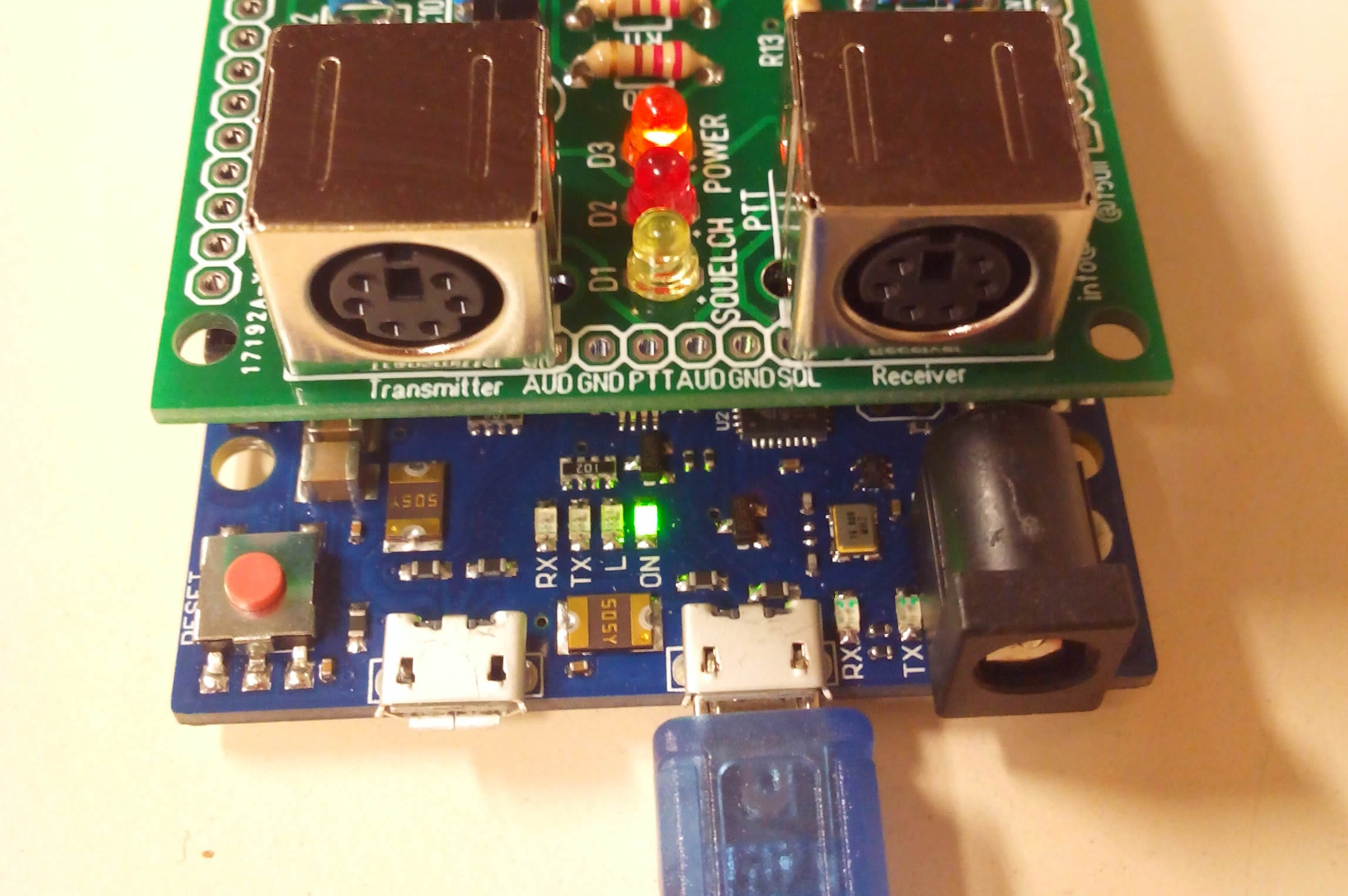
Synoptique d’un relais utilisant le “MultiMode Digital Voice Modem” (MMDVM)
En plus d’être accessibles aux bricoleurs ayant la fibre informatique… il s’agit de réalisation à coût faible. Je vous propose de suivre étape par étape toute la mise en œuvre. L’objectif est simple : Disposer d’un relais numérique UHF interconnecté via internet.
Le tutoriel est à lire sur plusieurs pages. Utiliser le sommaire et la navigation proposée en bas d’article pour vous faciliter la navigation.
Installation de la carte Arduino
Vous avez acheté votre carte Arduino DUE, et la première chose à faire est d’installer le logiciel d’édition IDE Arduino. Télécharger le fichier d’installation (86Mo pour la version 1.6.0 de l’IDE) sur la page https://www.arduino.cc/en/Main/Software
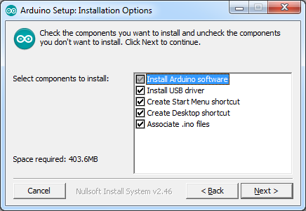
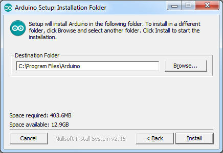
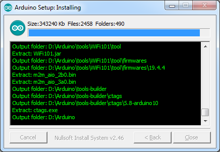
Installer le logiciel. Toutes les cases sont cochées notamment Install USB Driver.
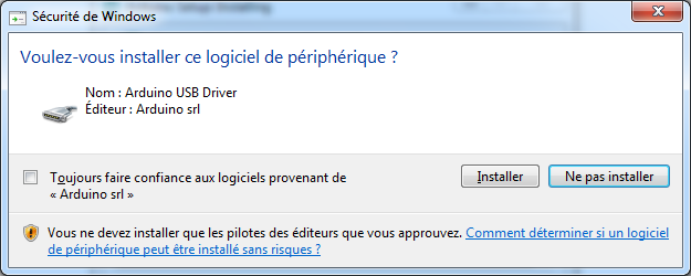
Plusieurs questions de sécurité d’installation du Driver USB sont posées. Bien sûr, nous répondons Installer.
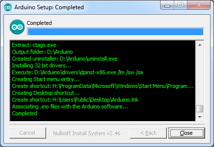
Le message Completed est affichée, l’installation est terminée, Cliquer sur Close.
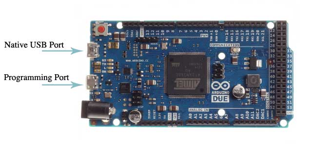
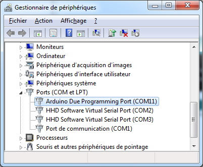
Brancher la carte Arduino DUE sur le port USB de programmation (coté connecteur d’alimentation externe), le Gestionnaire de périphérique ajoute un Ports série COM. Dans mon cas, un port COM11 (Arduino DUE Programming Port).
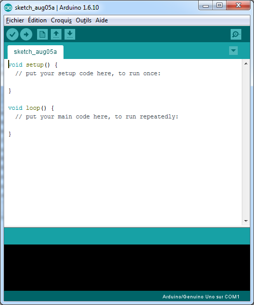
Depuis le menu démarré, vous pouvez lancer le logiciel Arduino
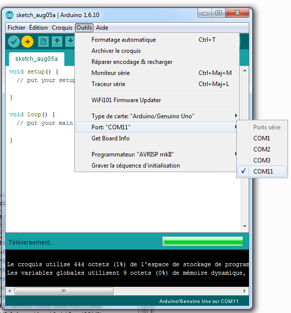
Choisissez le port série correspondant à votre liaison avec l’Arduino DUE, (ici COM11) dans le menu Outils / Ports.
Puis choisir Outils / Gestionnaire de carte. Le gestionnaire télécharge les définitions des cartes Arduino sur internet.
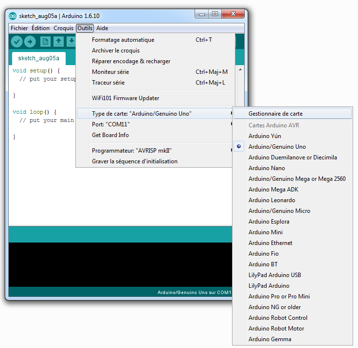
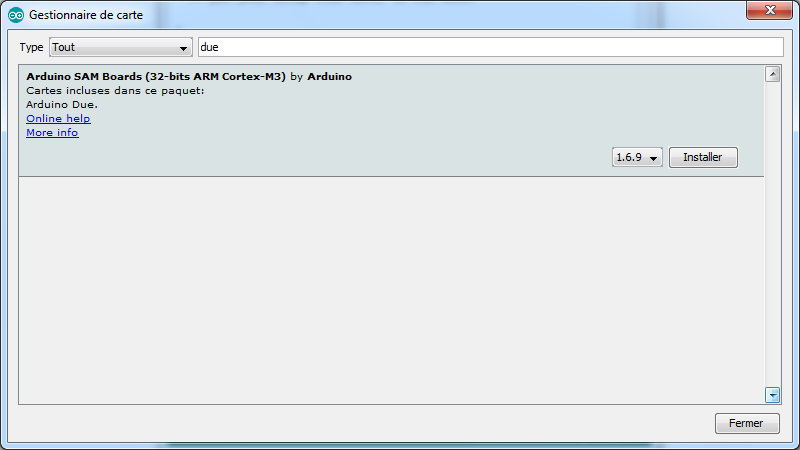
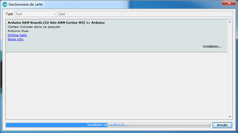
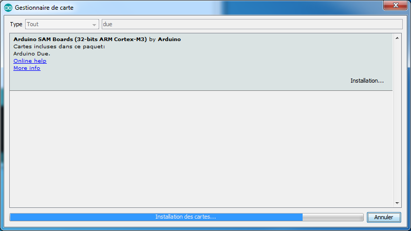
Dans le champ Filtrez la recherche, tapez due. Sélectionner la ligne Arduino SAM Boards (32-bits ARM Cortex-M3), et cliquer Installer.
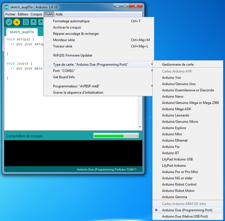
Sélectionner à présent en bas du menu Outils / Type de carte : “Arduino Due (Programming Port)”
Avant de programmer l’arduino avec le logiciel MMDVM, nous allons injecter un petit programme de test, pour vérifier que tout est correctement paramétré.
The first grouped order is about to be delivered. If you have an interest for any other grouped order, you can be alerted by email by adding your email to the site shop.f5uii.net

Merci F5UII pour toutes ces explications et votre travail sur le sujet. Une question à propos de ce relais MMDVM à base de ARDUINO DUE.
Est-il possible de la faire fonctionner ce relais en DMR autonome sans Rapberry PI ?
Cette question car nous avons un projet à MARSEILLE sur un site dépourvu de connection à Internet.
Merci pour votre retour
(Traduction)
Thank you F5UII for all these explanations and your work on the subject. A question about this MMDVM repeater based on ARDUINO DUE.
Is it possible to operate this repeater in standalone DMR without Raspebrry PI?
This question because we have a project in MARSEILLE on a site devoid of connection to Internet.
Thanks for your feedback
Merci Laurent,
Il faudra toujours un Raspberry Pi qui assure la fonction de logique du relais. Sans internet, le relais fonctionnera en local comme un relais analogique, en local, en utilisant le canal (TalkGroup) TG 9.
Dans ce cas, et même si cela ne semble pas nécessaire, il serait peut être nécessaire d’assurer une mise à l’heure du Raspberry Pi par une source externe (GPS ou RTC), afin qu’il ne dérive pas trop. Le Raspberry Pi se met à l’heure automatiquement par internet.
(Traduction)
Thank you Larry,
It will always require a Raspberry Pi that provides the repeater controler function of the repeater. Without the internet, the relay will operate locally as an analog relay, locally, when users connecting it by using the TG 9 (TalkGroup) channel.
In this case, and even if this does not seem necessary, i will advise to ensure that the Raspberry Pi is set to an external source (GPS or RTC) so that it does not drift too much. The Raspberry Pi automatically sets itself on the Internet.
Bonjour a tous je me permet de copier l’échange par mails avec Christian au sujet de mon souci pour que tous le monde en profite.
Tous d’abord merci du travaille effectuer pour la carte MMDVM… ainsi que SVXLink que j’ai aussi.
J’ai un souci sur la carte MMDVM : au branchement de l’Arduino la LED L clignote doucement , puis des le démarrage de MMDVM elle clignote rapidement ainsi que TX/RX qui clignote synchro.
Le logiciel ne reçois rien , j’ai bien fait la procédure de réglage du niveau sur la broche A0 suivant votre tuto, mais pas le moindre affichage de réception ni de LED SQUELCH allumer lors de la réception d’une émission.
Cela fait plus d’une semaine que je cherche sans n’avoir rien trouver de probant.
Si vous avez une idee ?
73 QRO
Romain Lepron F4HTU
Reponse de Christian :
Cela pourrait être résolu par la piste indiquée ici.
https://www.f5uii.net/compilation-installation-configuration-mmdvm-stm32f4xx/#comment-13080
Moi :
Merci de la réponse rapide
Donc le souci serait peut être que le TCXO n’envoie pas les bon niveau a l’Arduino.
Il a besoin de sa pour se verrouiller, si cela n’est pas fait aucune réception ne peut être lancer si j’ai bien compris ?
Je vais voir sa des maintenant
—
Je viens de court-circuiter C22
Effectivement javais 3v de niveau , maintenant j’ai bien 3.3V. Je vous joints la photos de l’oscilloscope, cela vous parait t-il correct ?
Par contre toujours ces LED TXRX qui clignote ensemble , c’est normal ?
Christian :
OK pour le trace temporelle du TCXO.
Concernant les LED : vérifier votre fichier config.h MMDVM
La frequence normalement fourni par Shopchip est 12.288
#define EXTERNAL_OSC 12288000

#define ARDUINO_DUE_NTH
(Translation)
Hello all I can copy the exchange by mails with Christian about my concern so that everyone benefits.
First of all thank you for the work done for the MMDVM card … as well as SVXLink that I also have.
I have a problem with the MMDVM card: when the Arduino is connected, the LED L flashes slowly, then the MMDVM start flashes quickly and TX / RX flashes sync.
The software does not receive anything, I did well the procedure of adjusting the level on pin A0 according to your tuto, but not the slightest reception display nor LED SQUELCH turn on when receiving a program.
I have been searching for more than a week without having found anything convincing.
If you have an idea ?
73 QRO
Romain Lepron F4HTU
Answer by Christian:
This could be solved by the track shown here.
https://www.f5uii.net/compilation-installation-configuration-mmdvm-stm32f4xx/#comment-13080
Me :
Thanks for the quick reply
So the worry may be that the TCXO does not send the right level to the Arduino.
He needs his to lock himself, if that is not done no reception can be thrown if I understand correctly?
I’ll see her now
—
I just shortcut C22
Actually I had 3v level, now I have 3.3V well. I attach you the photos of the oscilloscope, it seems to you correct?
By cons always those TXRX LEDs that blink together, is it normal?
Christian:
OK for the time trace of the TCXO.
About LEDs: check your config.h file MMDVM
The frequency normally provided by Shopchip is 12,288
#define EXTERNAL_OSC 12288000#define ARDUINO_DUE_NTH
Voila , je viens de paramétrer l’Arduino sur
define EXTERNAL_OSC 12288000Maintenant il faudra attendre ce soir pour voir si il reçois mon émission.
Petite question : la LED SQUELCH est commander par l’arduino a travers la detection RADIO-SQL quand le transistor mets la borne A7 au plus 3V ?
Que même quand le poste reçois une émission et qu’il passe le SQL a 5V , rien ne s’allume sur la carte.
Le clignotement frénétique et synchro des LED TX/RX est donc normal.
73 QRO
(Translation)
So, I just set the Arduino on define
EXTERNAL_OSC 12288000Now he’ll have to wait until tonight to see if he gets my show.
Small question: the LED SQUELCH is controlled by the arduino through the RADIO-SQL detection when the transistor puts terminal A7 at most 3V?
That even when the station receive a broadcast and it passes the SQL to 5V, nothing lights up on the card.
The frenzy and sync flashing of the TX / RX LEDs is therefore normal.
73 QRO
La LED Squelch est pilotée par l’arduino et sera allumée uniquement au décodage de signaux réceptionnés par MMDVM. Elle reste éteinte en effet pour tout autre signal non décodé par MMVDM (indépendant de RADIO-SQL et je crois bien non exploité en réalité).
Les LEDs TX et RX sur la platine Arduino clignotent et indiquent qu’il y a communication entre le modem MMDVM (arduino) et MMDVMHost. Ce dialogue série est initialisé par MMDVMHost. C’est donc bon signe…
La LED L clignote à une fréquence plus élevé lors que MMDMV tourne.
Il ne vous reste plus qu’à faire des essais avec émetteur et récepteur.
Bons essais !
(Translation)
The Squelch LED is controlled by the arduino and will only be lit when decoding signals received by MMDVM. It remains off for any other signal not decoded by MMVDM (independent of RADIO-SQL and I believe not really exploited in fact).
The TX and RX LEDs on the Arduino board blink and indicate that there is communication between the MMDVM modem (arduino) and MMDVMHost. This serial dialog is initialized by MMDVMHost. So it’s a good sign …
The LED L flashes at a higher frequency when MMDMV is running.
All you have to do now is test with transmitter and receiver.
Good trials!
Ok je teste ca ce soir
En espérant que le fait d’avoir le même ID sur le relais et dans le MD380 ne pose pas de souci…( juste le temps des test )
Par contre , ayant qu’un seul des deux poste radio FT-7800 , cela ne pose t-il pas de problème que je le raccorde seulement a RECEIVER pour mes test de réception ?
La carte peut elle juste recevoir sans émettre ou le portatif attend une confirmation du relais sur sa voie de réception ?
Merci beaucoup
(Translation)
Ok I test it tonight
Hoping that having the same ID on the relay and in the MD380 does not matter … (just test time)
On the other hand, having only one of the two FT-7800 radio sets, does not it matter that I only connect it to RECEIVER for my reception test?
Can the card just receive without transmitting or the handset waits for confirmation of the relay on its receiving channel?
thank you very much
Si vous connectez MMDVMHost à un master du réseau Brandmeister, normalement, l’ID du relais n’a pas besoin d’être forcément enregistré. Prenez tout de même un ID libre en consultant la base http://ham-digital.org/dmr-rptrreg.php#FRA
Il vaut mieux que les ID soient distincts, je suppose que cela poserait problématique.
Le relais doit être full-duplex. Cela n’ira pas si vous n’avez pas les deux postes. La section
[General]deMMDVM.inipréciseDuplex =1pour un relais.Pour le réglage de MMDVMHost vous aurez certainement déjà découvert mon article
https://www.f5uii.net/installation-calibration-adjustment-tunning-mmdvm-mmdvmhost-raspberry-motorola-gm360/
Si vous ne branché que le RX, vous pourriez avoir par chance quelques traces dans le log de MMDVMHost, mais le réglage de la partie réception sera impossible tant qu’une liaison Fullduplex ne soit établi. A l’inverse le poste unique peut servir au réglage de la chaine d’émission, par utilisation de MMDVMCal.
(Translation)
If you connect MMDVMHost to a Brandmeister network master, normally the repeater ID does not need to be a register one. Please take a free ID – have a look on http://ham-digital.org/dmr-rptrreg.php#FRA
It is better that the IDs are distinct, I suppose that would be problematic.
The repeater must be full-duplex. This will not happen if you do not have both transceivers. The
[General]section ofMMDVM.inispecifiesDuplex = 1for a repeater.For the MMDVMHost setting you may have already discovered my post :
https://www.f5uii.net/en/installation-calibration-adjustment-tunning-mmdvm-mmdvmhost-raspberry-motorola-gm360/
If you only connect the RX, you may have a few log lines in the MMDVMHost log, but you can not set the receive part until a full-duplex connection is established. Conversely, the single station can be used to adjust the transmission way, using MMDVMCal.
Ok
Je vais prendre l’ID d’un ami pour mon MD-380 histoire que cela ne pose pas de souci.
Je vais mettre le 7800 sur la chaine émission et un autres poste sur la chaine réception, c’est bien la dessus que je ne savais pas si il fallait une vrai liaison FULL-DUPLEX…
Je préférer poser la question pour mettre toute les chances de mon coté 🙂
Je vous donne des nouvelles ce soir , et peut être en DMR qui sais…
73 QRO++
OK
I will take a friend’s ID for my MD-380 so that it does not matter.
I’m going to put the 7800 on the transmission chain and another station on the reception chain, it is the subject, I did not know if it needed a real FULL-DUPLEX link …
I prefer to ask the question to put the odds of my side 🙂
I give you news tonight, and can be QRV in DMR who knows …
73 QRO ++
Hi.
I try to compile the program for the arduino due. Linux mint
My arduino ide (1.6.12) and Arduino SAM Boards (1.6.11).
The file to be edited, indicated in BUILD.txt, does not exist the directory that indicates.
I have modified the files in:
User /arduino/hardware/platform.txtalso
User /arduino/hardware/avr/platform.txtThere is no subdirectory
/ samThe following errors appear
--------------------------------------------Arduino:1.6.12 (Linux), Tarjeta:"Arduino Due (Programming Port)"
sketch/DMRDMOTX.cpp.o: In function `CDMRDMOTX::writeByte(unsigned char)':
sketch/DMRDMOTX.cpp:139: undefined reference to `arm_fir_interpolate_q15'
sketch/DMRTX.cpp.o: In function `CDMRTX::writeByte(unsigned char, unsigned char)':
sketch/DMRTX.cpp:268: undefined reference to `arm_fir_interpolate_q15'
sketch/DStarRX.cpp.o: In function `CDStarRX::samples(short*, unsigned short const*, unsigned char)':
sketch/DStarRX.cpp:294: undefined reference to `arm_q15_to_q31'
sketch/DStarRX.cpp:295: undefined reference to `arm_biquad_cascade_df1_q31'
sketch/DStarTX.cpp.o: In function `CDStarTX::writeByte(unsigned char)':
sketch/DStarTX.cpp:428: undefined reference to `arm_fir_interpolate_q15'
sketch/IO.cpp.o: In function `CIO::process()':
sketch/IO.cpp:163: undefined reference to `arm_fir_fast_q15'
sketch/IO.cpp:170: undefined reference to `arm_fir_fast_q15'
sketch/IO.cpp:177: undefined reference to `arm_fir_fast_q15'
sketch/IO.cpp:192: undefined reference to `arm_fir_fast_q15'
sketch/IO.cpp:199: undefined reference to `arm_fir_fast_q15'
sketch/IO.cpp.o:sketch/IO.cpp:214: more undefined references to `arm_fir_fast_q15' follow
sketch/P25RX.cpp.o: In function `CP25RX::samples(short*, unsigned short*, unsigned char)':
sketch/P25RX.cpp:107: undefined reference to `arm_q15_to_q31'
sketch/P25RX.cpp:108: undefined reference to `arm_biquad_cascade_df1_q31'
sketch/P25TX.cpp.o: In function `CP25TX::writeByte(unsigned char)':
sketch/P25TX.cpp:150: undefined reference to `arm_fir_interpolate_q15'
sketch/P25TX.cpp:152: undefined reference to `arm_fir_fast_q15'
sketch/YSFRX.cpp.o: In function `CYSFRX::samples(short*, unsigned short*, unsigned char)':
sketch/YSFRX.cpp:103: undefined reference to `arm_q15_to_q31'
sketch/YSFRX.cpp:104: undefined reference to `arm_biquad_cascade_df1_q31'
sketch/YSFTX.cpp.o: In function `CYSFTX::writeByte(unsigned char)':
sketch/YSFTX.cpp:139: undefined reference to `arm_fir_interpolate_q15'
collect2: error: ld returned 1 exit status
exit status 1
Error compilación en tarjeta Arduino Due (Programming Port).
-------------------------------
Any ideas?
regards
Hello,
It is as if you did not install the Arduino SAM Boards package.
Have you follow the advices given by M1GEO ? (https://github.com/g4klx/MMDVM/blob/master/BUILD.txt) :
Regards
Christian F5UII
There is no “C:\Users\User\AppData\” on my machine, I have tried all (user) on my machine.
(Traduction)
Il n’y a pas de “C:\Users\User\AppData\” sur ma machine, J’ai essayé tous les utilisateurs de ma machine
Craig,
Under windows, type directly %appdata% , bottom left in “Search programs and files” and Enter. You will be directly in your user Appdata\Roaming directory. From there, you will be able to access the right directory
(Traduction)
Craig,
Sous Windows, tapez directement %appdata%, en bas à gauche dans “Rechercher les Programmes et fichiers” et entrez. Vous serez directement dans le répertoire de votre utilisateur Appdata\Roaming.
Depuis là, vous pourrez accéder au bon répertoire
Bonjour Christian,
Je possède un shield MMDVM nucleo V2 acheté chez vous il y a quelques temps. Mes nombreuses tentatives de faire fonctionner cette interface sur ma carte nucleo F446RE sont jusqu’ici restées infructueuses.
Dernière tentative en cours:
– J’ai compilé la dernière version en date du firmware pour la carte nucleo, avec les paramètres suivants (Config.h):
// For 12 MHz#define EXTERNAL_OSC 12000000
// For 12.288 MHz
// #define EXTERNAL_OSC 12288000
// For 14.4 MHz
// #define EXTERNAL_OSC 14400000
// For 19.2 MHz
// #define EXTERNAL_OSC 19200000
// Use pins to output the current mode via LEDs
#define MODE_LEDS
// For the original Arduino Due pin layout
// #define ARDUINO_DUE_PAPA
#if defined(STM32F1)
// For the SQ6POG board
#define STM32F1_POG
#else
// For the ZUM V1.0 and V1.0.1 boards pin layout
#define ARDUINO_DUE_ZUM_V10
#endif
// For the SP8NTH board
// #define ARDUINO_DUE_NTH
// For ST Nucleo-64 STM32F446RE board
#define STM32F4_NUCLEO_MORPHO_HEADER
// #define STM32F4_NUCLEO_ARDUINO_HEADER
// Use separate mode pins to switch external channel/filters/bandwidth for example
#define MODE_PINS
// For the VK6MST Pi3 Shield communicating over i2c. i2c address & speed defined in i2cTeensy.cpp
// #define VK6MST_TEENSY_PI3_SHIELD_I2C
// Pass RSSI information to the host
#define SEND_RSSI_DATA
// Use the modem as a serial repeater for Nextion displays
#define SERIAL_REPEATER
// To reduce CPU load, you can remove the DC blocker by commenting out the next line
#define USE_DCBLOCKER
// Constant Service LED once repeater is running
// Do not use if employing an external hardware watchdog
// #define CONSTANT_SRV_LED
// Use the YSF and P25 LEDs for NXDN
#define USE_ALTERNATE_NXDN_LEDS
// Use the D-Star and DMR LEDs for POCSAG
#define USE_ALTERNATE_POCSAG_LEDS
// Use the D-Star and YSF LEDs for FM
#define USE_ALTERNATE_FM_LEDS
– J’ai installé et compilé sur ma Raspberry Pi B+ V1.2 les dernières version en date de MMDVMHost et MMDVMCal, sans aucune erreur lors de la compilation.
– J’ai chargé la dernière version en date des fichiers pour l’afficheur Nextion 2.4″, câblé sur votre interface et avec lequel MMDVMHost communique sans problème (voir plus loin MMDVM.ini).
– J’utilise un TAIT TM8105 dans lequel j’ai chargé le profil radio disponible sur votre site, en changeant uniquement le couple de fréquences d’émission/réception.
– J’ai suivi à la lettre le brochage sur la prise accessoires du mobile TAIT, en ajoutant cependant une résistance variable me permettant de réduire le niveau audio envoyé sur l’interface nucleo.
– J’exécute MMDVMCal et à l’aide de mon MD380 relié à une charge “non rayonnante” j’arrive à atteindre un BER de 0%:
DMR voice header receivedDMR voice header received
DMR audio seq. 0, FEC BER % (errs): 0.000% (0/141)
DMR audio seq. 1, FEC BER % (errs): 0.000% (0/141)
DMR audio seq. 2, FEC BER % (errs): 0.000% (0/141)
DMR audio seq. 3, FEC BER % (errs): 0.000% (0/141)
DMR audio seq. 4, FEC BER % (errs): 0.000% (0/141)
DMR audio seq. 0, FEC BER % (errs): 0.000% (0/141)
DMR audio seq. 1, FEC BER % (errs): 0.000% (0/141)
DMR audio seq. 2, FEC BER % (errs): 0.000% (0/141)
DMR audio seq. 3, FEC BER % (errs): 0.000% (0/141)
DMR audio seq. 4, FEC BER % (errs): 0.000% (0/141)
DMR audio seq. 5, FEC BER % (errs): 0.000% (0/141)
DMR audio seq. 0, FEC BER % (errs): 0.000% (0/141)
DMR audio seq. 2, FEC BER % (errs): 0.000% (0/141)
DMR audio seq. 3, FEC BER % (errs): 0.000% (0/141)
DMR audio seq. 4, FEC BER % (errs): 0.000% (0/141)
DMR audio seq. 5, FEC BER % (errs): 0.000% (0/141)
DMR audio seq. 0, FEC BER % (errs): 0.000% (0/141)
DMR audio seq. 1, FEC BER % (errs): 0.000% (0/141)
DMR audio seq. 2, FEC BER % (errs): 0.000% (0/141)
DMR audio seq. 3, FEC BER % (errs): 0.000% (0/141)
DMR audio seq. 4, FEC BER % (errs): 0.000% (0/141)
DMR audio seq. 5, FEC BER % (errs): 0.000% (0/141)
DMR audio seq. 0, FEC BER % (errs): 0.000% (0/141)
DMR audio seq. 1, FEC BER % (errs): 0.000% (0/141)
DMR audio seq. 2, FEC BER % (errs): 0.000% (0/141)
DMR audio seq. 3, FEC BER % (errs): 0.000% (0/141)
DMR audio seq. 4, FEC BER % (errs): 0.000% (0/141)
DMR audio seq. 5, FEC BER % (errs): 0.000% (0/141)
DMR voice end received, total frames: 28, bits: 3948, errors: 0, BER: 0.0000%
– Côté MMDVM.ini, j’ai bien passé RXInvert à 1 et laissé le RXLevel inchangé car j’obtiens une BER de 0 avec la valeur par défaut. J’ai désactivé tous les modes sauf FM et DMR dans un premier temps, pour limiter les sources de problèmes et aussi pour soulager le processeur de la Raspberry Pi.
[Modem]Port=/dev/ttyACM0
# Port=/dev/ttyAMA0
# Port=\\.\COM4
Protocol=uart
# Address=0x22
TXInvert=1
RXInvert=1
PTTInvert=0
TXDelay=100
RXOffset=0
TXOffset=0
DMRDelay=90
RXLevel=50
TXLevel=50
RXDCOffset=0
TXDCOffset=0
RFLevel=100
# CWIdTXLevel=50
# D-StarTXLevel=50
# DMRTXLevel=50
# YSFTXLevel=50
# P25TXLevel=50
# NXDNTXLevel=50
# POCSAGTXLevel=50
# FMTXLevel=50
RSSIMappingFile=RSSI.dat
UseCOSAsLockout=0
Trace=0
Debug=1
[DMR]
Enable=1
Beacons=0
BeaconInterval=60
BeaconDuration=3
ColorCode=1
SelfOnly=0
EmbeddedLCOnly=0
DumpTAData=1
# Prefixes=234,235
# Slot1TGWhiteList=
# Slot2TGWhiteList=
CallHang=3
TXHang=4
# ModeHang=10
# OVCM Values, 0=off, 1=rx_on, 2=tx_on, 3=both_on, 4=force off
# OVCM=0
[FM]
Enable=1
Callsign=F4xxx
CallsignSpeed=20
CallsignFrequency=1000
CallsignTime=10
CallsignHoldoff=0
CallsignHighLevel=50
CallsignLowLevel=20
CallsignAtStart=1
CallsignAtEnd=1
CallsignAtLatch=0
RFAck=K
ExtAck=N
AckSpeed=20
AckFrequency=1750
AckMinTime=4
AckDelay=1000
AckLevel=50
# Timeout=180
TimeoutLevel=80
CTCSSFrequency=88.4
CTCSSThreshold=30
# CTCSSHighThreshold=30
# CTCSSLowThreshold=20
CTCSSLevel=20
KerchunkTime=0
HangTime=7
AccessMode=1
COSInvert=0
RFAudioBoost=1
MaxDevLevel=90
ExtAudioBoost=1
[DMR Network]
Enable=0
# Type may be either 'Direct' or 'Gateway'. When Direct you must provide the Master's
# address as well as the Password, and for DMR+, Options also.
Type=Gateway
Address=127.0.0.1
Port=62031
Local=62032
# Password=P@ssw0rd1234
Jitter=360
Slot1=1
Slot2=1
# Options=
# ModeHang=3
Debug=0
[Nextion]
Port=modem
#Port=/dev/ttyAMA0
Brightness=50
DisplayClock=1
UTC=0
#Screen Layout: 0=G4KLX 2=ON7LDS
ScreenLayout=2
IdleBrightness=20
– Tous les autres modes ont leur paramètre Enable à 0.
– J’ai installé le tableau de bord MMDVM embarqué “web”, permettant de confirmer que le mode DMR est bien actif, et que le CPU n’est pas à 100% lors de la réception d’une transmission en DMR.
– J’ai câblé un haut-parleur amplifié sur la sortie AUDIOTX de l’interface nucleo.
J’espère avoir détaillé au mieux les conditions de test.
J’observe le fonctionnement suivant:
– Lorsque j’émets en analogique, et avec le bon CTCSS, mon MMDVM affiche bien FM, la LED PTT s’allume et il retransmet le signal audio (sur le haut-parleur).
– Lorsque j’émets en DMR (code couleur 1, timeslot 1, en simplex sur le groupe 99), le MMDVM reste dans l’état “IDLE”.
Voyez-vous une erreur dans ma config ou des choses à vérifier?
(Translation)
Hello Christian,
I own a MMDVM nucleo shield V2 that I bought from your shop a few times ago. My many attempts to get this interface to work with my nucleo F446RE board have so far been unsuccessful.
Last attempt in progress :
– I’ve compiled the latest nucleo firmware version, with the following parameters (Config.h):
(code in upper french part)
– I’ve installer and compiled the latest MMDVMHost and MMDVMCal versions on my Raspberry Pi B+ V1.2, without any error or warning.
– I’ve uploaded the latest Nextion display files, which is wired to the nucleo shield, and with whom MMDVMHost communicates without any problem through the Raspberry Pi(see MMDVM.ini below).
– I use a TM8105 with the radio profile you provide on your website, in which I only have edited the receiving/transmitting frequencies.
– I’ve followed the wiring word by word on the accessory connector, on which I’ve only added a variable resistor in order to adjust the audio level fed to the nucleo shield.
– I can execute MMDVMCal, and with my MD380 connected to a dummy load and a few adjustments, I can get à 0% BER:
(log in upper french part)
– On the MMDVM.ini side, I’ve set RXInvert to 1 and left RXLevel unchanged because I already have a 0% BER thanks to the variable resistor, with the default RX level value. I also have disabled all modes but FM and DMR at first, in order to exclude fault sources and also to limit the CPU load on my Raspberry Pi.
(config in uppr french part)
– All other modes have their Enable setting set to 0.
– I’ve installed the embedded MMDVM dashboard, that allows me to certify that the DMR mode is really activated, and that the CPU load is well below 100%while receiving a DMR transmission.
– I’ve wired an amplified loudspeaker to the AUDIOTX output.
I hope I’ve described the test setup as well as possible.
Here are my observations:
– Analog transmissions, with the appropriate CTCSS, are correctly detected by my MMDVM. “FM” is displayed on the LCD, the PTT LED is lit and the audio signal is routed to the audio output (on the loudspeaker).
– DMR transmissions (color code 1, timeslot 1, simplex to TG 99), don’t affect the MMDVM, which remains in “IDLE” state.
Do you see any mistake in this setup, or do you have any idea of other things I should check?
Bonjour Ludovic,
C’est dans un premier temps une bonne chose que le relais FM fonctionne. Cela dédouane pas mal de chose. Rapidement, quelques pistes que je vous invite à creuser /tester :
1) Le paramètre de configuration #define ARDUINO_DUE_ZUM_V10 devrait être commenté puisque cet une STM32 qui tourne et non par un Arduino.
2) Je n’ai pas de certitude, mais je pense qu’un accès à un serveur DMR serait à mettre en place dans la configuration de MMDVMHost . Je ne connais pas précisément le fonctionnement de Gateway/Direct
3) Un test pourrait être fait en mettant en route la balise cyclique de DMR (Beacon et BeaconInterval en minutes), cela permettrait de confirmer la partie émission DMR
4) Placer les différents Debug=1 et consulter le log de MMDVMHost pour constater le comportement.
Bonne recherche, 73.
Christian
(Translation)
Hello Ludovic,
It’s a good thing that the FM repeater works in any case. It clears a lot of things. Quickly, some ideas that I invite you to explore/test:
1) The configuration parameter #define ARDUINO_DUE_ZUM_V10 should be commented since it is an STM32 that runs and not an Arduino.
2) I am not sure, but I think that an access to a DMR server should be set up in the MMDVMHost configuration. I don’t know exactly how Gateway/Direct works
3) A test could be done by starting the cyclic beacon of DMR (Beacon and BeaconInterval in minutes), that would allow to confirm the DMR emission part
4) Set the different Debug=1 and check the MMDVMHost log to see the behaviour.
Good luck with your investigation, 73.
Christian
Bonjour Christian, et merci pour les propositions d’essais à réaliser.
Entre temps, j’ai trouvé la solution à mon problème:
– Le test RX DMR effectué avec MMDVMCal est en simplex, alors que MMDVMHost est configuré par défaut en duplex. Le mode de fonctionnement du système DMR est différent selon l’utilisation en simplex ou duplex. Je m’en suis rendu compte en modifiant sans grande conviction (au début) le paramètre Duplex=1 dans MMDVM.ini. En le mettant à 0, MMDVMHost a enfin détecté de l’émission simplex du MD380. Première étape de franchie! ;
– J’ai ensuite redéfini la paramètre Duplex à 1. Dans ce mode de fonctionnement, le poste DMR s’attend à voir l’émission du relais qui confirme l’établissement de la liaison radio, ce qui n’était pas le cas puisque je n’avais pas encore relié de poste pour la partie émission.
J’ai alors paramétré le MD380 en duplex (fréquences RX et TX différentes), connecté un second TM8105 pour la partie émission du relais et suivi à la lettre, une fois de plus, vos explications. La configuration logicielle et radio étant en accord avec le mode d’utilisation du MD380, j’ai enfin pu voir mon émission détectée par MMDVMHost.
Maintenant, je bloque sur la connexion au brandmeister. J’ai trouvé trois adresses de connexion différentes avec mon moteur de recherche, mais aucune ne fonctionne.
J’ai ça dans MMDVM.ini:
[DMR Network]Enable=1
# Type may be either 'Direct' or 'Gateway'. When Direct you must provide the Ma$
# address as well as the Password, and for DMR+, Options also.
Type=Gateway
Address=master.dstar.su
Port=62031
#Local=62032
Password=passw0rd
Jitter=360
Slot1=1
Slot2=1
# Options=
# ModeHang=3
Debug=0
Sur MMDVM-Dashboard, l’adresse du serveur reste sur fond rouge avec l’infobulle qui indique “Master not connected”.
Le ping depuis la Raspberry Pi répond:
pi@raspberrypi:/opt/MMDVMHost $ ping master.dstar.suPING brandmeister.r2aee.net (44.188.129.250) 56(84) bytes of data.
64 bytes from 44.188.129.250 (44.188.129.250): icmp_seq=1 ttl=46 time=90.5 ms
64 bytes from 44.188.129.250 (44.188.129.250): icmp_seq=2 ttl=46 time=82.8 ms
64 bytes from 44.188.129.250 (44.188.129.250): icmp_seq=3 ttl=46 time=107 ms
^C
--- brandmeister.r2aee.net ping statistics ---
3 packets transmitted, 3 received, 0% packet loss, time 4ms
rtt min/avg/max/mdev = 82.820/93.438/107.035/10.107 ms
(Translation)
Hi Christian, and thanks for the tests suggestions.
In the meantime, I’ve found the solution to my problem:
– The DMR RX test performed with MMDVMCal is made in simplex mode, while MMDVMHost is configured for duplex use by default. I realized that by modifying the Duplex=1 setting halfheartedly (at first) in MMDVM.ini. By setting it to 0, MMDVMHost finally detected the simplex transmission from my MD380. First step completed! ;
– I’ve then reset the Duplex parameter to 1. In this mode, the DMR transceiver waits to receive the relay’s transmission that confirms the good process of the radio link, which was not the case as there was no radio on the transmission side
So, I’ve set the MD380 to duplex (different RX & TX frequencies), connected another TM8105 for the transmission part of the relay and followed your explanations to the letter once again. The software and radio configuration being in accordance with the MD380 settings, I was finally able to see my transmission detected by MMDVMHost.
Now, I’m stuck at the brandmeister connection. I’ve found 3 server addresses with my favorite search engine, but none of them seem to work.
Here is what I’ve set in MMDVM.ini:
[DMR Network]Enable=1
# Type may be either 'Direct' or 'Gateway'. When Direct you must provide the Ma$
# address as well as the Password, and for DMR+, Options also.
Type=Gateway
Address=master.dstar.su
Port=62031
#Local=62032
Password=passw0rd
Jitter=360
Slot1=1
Slot2=1
# Options=
# ModeHang=3
Debug=0
MMDVM-Dashboard shows the server address on a red background, with the tool-tip indicating “Master not connected”.
I get replies from the server with a ping from the Raspberry Pi:
pi@raspberrypi:/opt/MMDVMHost $ ping master.dstar.suPING brandmeister.r2aee.net (44.188.129.250) 56(84) bytes of data.
64 bytes from 44.188.129.250 (44.188.129.250): icmp_seq=1 ttl=46 time=90.5 ms
64 bytes from 44.188.129.250 (44.188.129.250): icmp_seq=2 ttl=46 time=82.8 ms
64 bytes from 44.188.129.250 (44.188.129.250): icmp_seq=3 ttl=46 time=107 ms
^C
--- brandmeister.r2aee.net ping statistics ---
3 packets transmitted, 3 received, 0% packet loss, time 4ms
rtt min/avg/max/mdev = 82.820/93.438/107.035/10.107 ms
Je me réponds à moi-même, et pour éviter de vous faire “perdre” du temps pour répondre. La solution: il faut récupérer DMRGateway sur le GIT de G4KLX, le compiler (de la même manière que pour MMDVMHost et MMDVMCal), et l’exécuter. DMRGateway agit en tant qu’interface entre MMDVMHost et brandmeister (entre autre).
MMDVM.ini:
[DMR Network]Enable=1
# Type may be either 'Direct' or 'Gateway'. When Direct you must provide the Master's
# address as well as the Password, and for DMR+, Options also.
Type=Gateway
Address=127.0.0.1
Port=62031
Local=62032
Password=P@ssw0rd
Jitter=360
Slot1=1
Slot2=1
# Options=
# ModeHang=3
Debug=1
DMRGateway.ini:
[DMR Network 1]
Enabled=1
Name=BM
Address= 2081.master.brandmeister.network
Port=62031
# Local=3352
# Local cluster
TGRewrite=1,9,1,9,1
# Reflector TG on to slot 2 TG9
TGRewrite=2,9,2,9,1
# Reflector control command slot 2 94000->4000 to 95000->5000
PCRewrite=2,94000,2,4000,1001
# Echo on RF slot 1 TG9990 to network slot 1 9990
TypeRewrite=1,9990,1,9990
SrcRewrite=1,9990,1,9990,1
# Reflector status returns
SrcRewrite=2,4000,2,9,1001
# Dynamic rewriting of slot 2 TGs 90-999999 to TG9 to emulate reflector behaviour
TGDynRewrite= 2,90,4000,5000,9,999910,9990
# For normal repeater operation disable TGDyn coment out the above line
# After that remove the coments below
# PassAllTG=1
# PassAllTG=2
# Pass all of the other private traffic on slot 1 and slot 2
PassAllPC=1
PassAllPC=2
Password=passw0rd
Location=1
Debug=1
L’adresse locale apparaît toujours sur fond rouge sur le MMDVM-Dashboard mais je vois mon relais sur le tableau de bord brandmeister ainsi que le journal des communications radio locales, donc la connexion s’effectue bien.
Je continue de bricoler sans polluer le fil des commentaires. Merci encore pour toutes les infos que vous partagez sur votre site!
(Translation)
I reply to myself, and also to save you from wasting time writing your answer. Here’s the solution: get DMRGateway from G4KLX’s GIT, compile it (just like MMDVMHost and MMDVMCal), and run it. DMRGateway acts as a gateway between MMDVMHost and brandmesiter (among others). [See my current settings above in the French message.]
The local address still appears with red background on MMDVM-Dashboard but I see my relay on the brandmesiter dashboard as well as the local radiocommunication log, so the connection is successful.
I’ll keep tinkering without bugging you. Thanks again for all the informations you share on your website!