
Intro
DATV: How to encode in h.265 with an external HDMI encoder
Notez qu’Evariste est actuellement (mai 2020) au travail pour diminuer les délais d’encodage, et faire en sorte que le flux soit plus conforme aux normes DVB-S2, DVB-S (Voir le tweet de @f5oeo à ce sujet). On attend toujours avec impatiente la livraison de ses développements…
This page is the official rules established for usage of the wideband transponder of the QO-100 satellite. March 2020 edition. See the BATC website for the current version.
Due to the very large number of potential users, all transmitting stations should monitor the wideband spectrum monitor and the co-ordination chat window that has been established by AMSAT-DL and the BATC at https://eshail.batc.org.uk/wb/
Transponder Usage
En règle générale, le transpondeur ne doit être utilisé que pour des tests et des contacts de courte durée. Les seules transmissions de longue durée (plus de 10 minutes) devraient être :
- Le canal de la balise TV en liaison montante depuis le Qatar ou Bochum.
- Vidéo des séances en direct de l’AMSAT et des conférences télévisées d’amateurs de portée générale. Exemples possibles :
- Conférences nationales de l’AMSAT
- Conventions nationales sur la télévision amateur
Les contenus suivants sont inacceptables :
- Enregistrements ou diffusion d’événements qui ne concernent pas explicitement les satellites amateurs ou la télévision amateur
- Transmission de tout support protégé par des droits d’auteur (tels que des films ou chaînes de télévision)
- Transmission répétitive de vidéos d’essai, sauf si elles sont essentielles pour l’alignement des équipements
La retransmission de signaux de télévision amateur terrestre est déconseillée, sauf si le contenu présente un intérêt exceptionnel pour les radioamateurs.
Puissance de transmission
Toutes les transmissions doivent utiliser en voie montante le minimum de puissance possible. Les transmissions QPSK doivent avoir un signal de liaison descendante avec une densité de puissance inférieure d’au moins 1 dB à celle de la balise – Le système de monitoring du spectre disponible en ligne permet aux utilisateurs de régler leur puissance d’émission pour y parvenir. Les transmissions avec des débits inférieurs à 333 kS utilisant 8PSK, 16 APSK ou 32 APKS doivent utiliser la puissance minimale nécessaire pour obtenir une bonne réception.
Modes de transmission
Les transmissions doivent utiliser le DVB-S2 dans la mesure du possible. Pour les transmissions en définition standard classique, 2 MS est le débit maximum de symboles qui doit être utilisé de facto.
Pour permettre un décodage facile, les PID DVB suivants sont recommandés : Vidéo 256, Audio 257, PMT 32 ou 4095, PCR 256 ou 258. Le nom du service doit correspondre à l’indicatif d’appel. Les PID PMT 4000 – 4010 ne doivent pas être utilisés.
Les mercredis (heure UTC), les expérimentateurs sont encouragés à essayer d’autres modes – peut-être 6 MS utilisant l’ensemble du transpondeur pendant de brèves périodes (moins de 10 minutes). Il est essentiel que les utilisateurs annoncent leurs essais sur la page du salon de discussion (chat), et qu’ils la surveillent en permanence.
Les expérimentations utilisant des modes inhabituels (par exemple ranging) doivent utiliser le segment inférieur de 1,5 MHz de la partie DATV large et étroit (‘’Wide and Narrow DATV’’).
Balise
La balise (Beacon) émet en continu (10491,5 MHz, DVB-S2, SR 1500 kS) pour fournir un signal de test et permettre aux nouveaux utilisateurs d’aligner précisément leurs antennes.
Plan de bande

QO-100 Es’hail-2 Wideband Spectrum Monitor
- Les transmissions DATV étroites doivent être limitées à la section DATV étroite (‘’Narrow DATV’), mais peuvent utiliser la section DATV large et étroite (‘’Wide and Narrow DATV’’) si la section DATV étroite est entièrement occupée.
- Une liaison montante de maintenance occupant la bande 10494,0 MHz – 10497,0 MHz sera utilisée très occasionnellement ; les utilisateurs sont priés de lui donner la priorité absolue lorsqu’ils sont avertis.
- Les fréquences ponctuelles recommandées pour divers usages et débits (SR) sont indiquées ci-dessous.
| Mode | Symbol Rate SR (/s) | Fréq Montée MHz | Fréq
Descente MHz |
Notes |
| Balise | 1500 kS | 2402.0 | 10491.5 | Balise DVB-S2 FEC 4/5 |
| Large | 1 MS | 2403.75 | 10493.25 | Les transmissions 1.5 MS et 2 MS doivent utiliser cette partie de la bande |
| Large | 1 MS | 2405.25 | 10494.75 | |
| Large | 1 MS | 2406.75 | 10496.25 | |
| Etroit | 333 kS | 2403.25 | 10492.75 | Utilisez ces 14 fréquences pour 500 kS, 333 kS et 250 kS
Utilisez d’abord les fréquences supérieures à 10497.0 |
| Ensuite, tous les 500 kHz jusqu’à | ||||
| Etroit | 333 kS | 2409.75 | 10499.25 | |
| Très étroit | 125 kS | 2403.25 | 10492.75 | Utilisez ces 27 fréquences pour 125 kS, 66 kS et 33 kS
Utilisez d’abord les fréquences supérieures à 10497.0 |
| Ensuite, tous les 250 kHz jusqu’à | ||||
| Très étroit | 125 kS | 2409.75 | 10499.25 | |
- Montée 2401.0 – 2410.0 MHz RHCP, Descente 10490.5 – 10499.5 MHz Horizontal.
Following my previous article on the transmission to the Qatar Oscar 100 satellite with SDR technology (LimeSDR, Adalm pluto) which was dedicated to the narrow-band transponder transmission (SSB and modes with spectral width less than 2.7 kHz), here is an article that should this time interest those who are willing to embark on the digital amateur television program, commonly called DATV (Digital Amateur Television).
As you may have read so far, I have a LimeSDR-mini but now also an Adalm Pluto. During one of my conferences (in french – see Amsat Francophone Conference), I had the occasion to compare the two equipments, their advantages and disadvantages. I had the experience to transmit in DATV to QO100 with both the LimeSDR-mini and the Adalm Pluto. Both models work very well, but I will focus in this article on the use of the Adalm Pluto, because finally it is today the solution that is the easiest to implement. Indeed, to transmit with LimeSDR, a Raspberry Pi is necessary. In the case of the Adalm Pluto and especially thanks to the developments of a specific firmware of Evariste F5OEO, we do without this nanocomputer, the Adalm rather embedding the software directly.
In this article, as usual, we will go step by step through all the operations described as precisely as possible.
I use the Windows operating system. I won’t go into the details of the operation of the transmission modes themselves, not being a specialist in the fundamentals. My goal is to bring to your knowledge all the steps that will allow you to build your own transmitting station, and transmit images. It is possible that the software evolving, certain functions, or operations themselves are to be made evolve. Do not hesitate to submit your questions, problems of implementation directly in comment of the article.
Here is the diagram of principle which we will implement, to transmit our DATV videos to the QO-100 satellite.

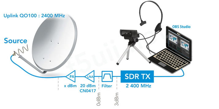
Schematic diagram of a DATV broadcast with OBS Studio and Adalm Pluto or LimeSDR
I don’t come back in this article to the basis of adjustment of dishes, antennas, transmitter that you find in my previous articles ( Receiving Qatar Oscar 100 satellite with SDR Console , The transmission over Qatar Oscar 100 satellite with SDR Console).
Let us remind in the preamble that radio broadcasting is regulated at the international level, at the national level and that only holders of class 1 and class 2 amateur radio licences are authorized to transmit on the allocated frequency bands.
This article is “multi-page”, to browse from one page to another or directly from the table of contents to the desired page.

The Adalm-Pluto also called PlutoSDR is an SDR transceiver offered by Analog Device at a relatively low price. It is presented as a platform for learning for students in the fields of science, technology or engineering.
Various software such as MATLAB or Simulink are graphical user interfaces (GUI) for applied developments.But in order to transmit in DATV we are not going to start on the road to development ourselves, since others are doing it for us.
Based on the AD9363, it is capable of generating or receiving analog RF signals from 325 to 3800 MHz, and up to 61.44 mega samples per second (MSPS) with a bandwidth of 20 MHz.
Acquiring Adalm Pluto
Obviously, the first thing is to acquire the equipment. Several suppliers make the box available, at different prices. I let you check the delivery conditions and customs taxes applicable by these intermediaries.
- Aliexpress
- Amazon
- Ebay – German seller who provides the modified PlutoSDR with the TCXO of good stability already installed – and on request the F5OEO firmware installed
- Mouser in the USA
- Passion radio in France
Improving the functioning and stability of Adalm Pluto
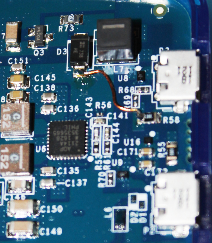
I am using an Adalm Pluto with hardware Revision B (See its label: PCB Rev.). You can observe – in any case in SSB transmission with SDR Console – from time to time crashes of the USB link. These easily disappear by applying a minor modification to the board. Either you change the resistance value of R88 from 1k to 10k, as indicated on the wiki website of Analog Device

Improving stability
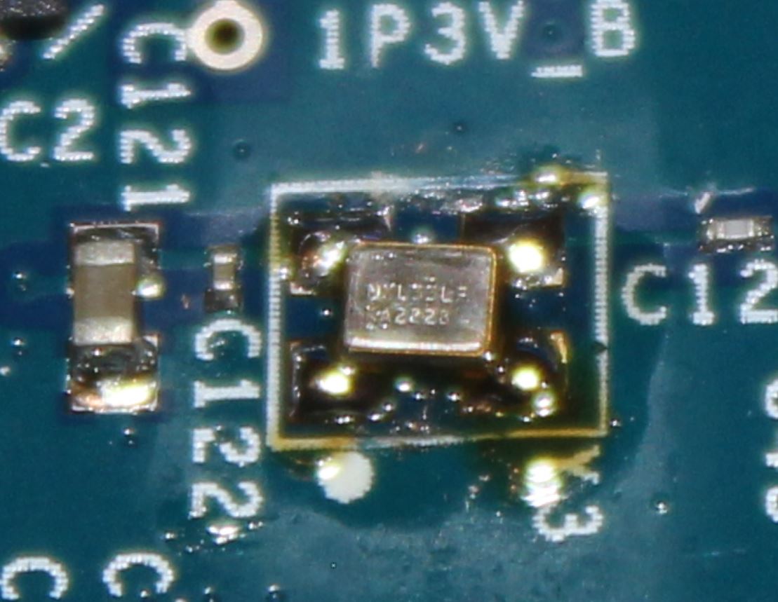
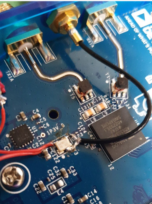
Replace crystal TCXO
Smaller than the original RAKON (3.2 x 2.5), the TCXO ABRACON ASTX-13-C-40.000MHz-I05-T is supplied with 1.8V like the original, its dimensions are 2.0 x 1.6 mm. It has an announced stability of +/- 0.5ppm. Some people advise to take advantage of this by placing the TCXO in a location that is less subject to temperature rises. I invite you to read Lucien F1TE’s (french) article on this subject.
TCXO ABRACON replacing the RAKON one
You can find this TCXO ABRACON at the major distributors of electronic components but also some other resellers:
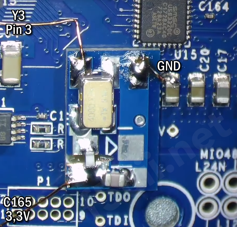
Murata TCXO 0.2ppm 3.0V
Another alternative is to use the TCXO MURATA XNCLH40M000THJA1P0 which is given at +/- 0.2ppm, but with a dimension of 5.0 x 3.2 mm and is powered by 3.0V. DM4DS to propose a small adapter board (a divider bridge to pass the 3.3V power supply point (recovered on C165) as well as a video explaining the power supply points and connections.
Injecting an external reference signal
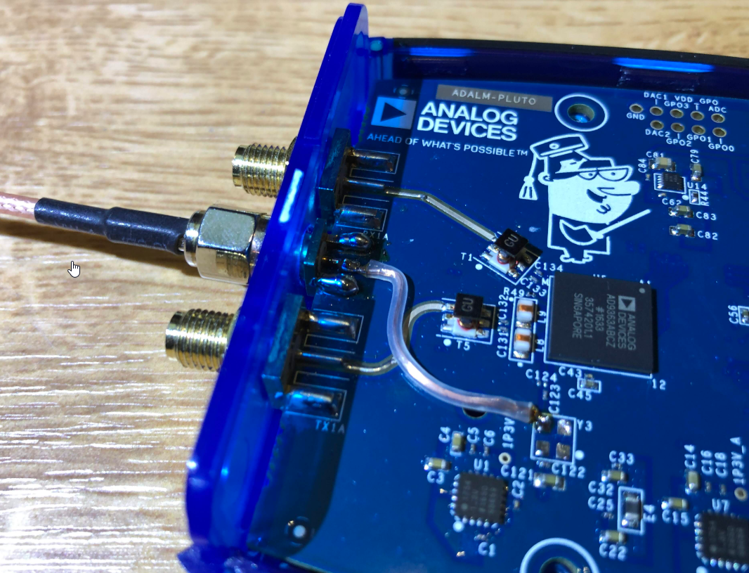
DL4TMA : Adding an external SMA connector
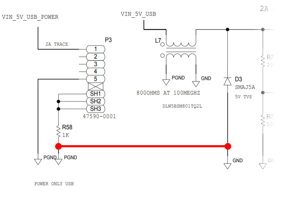
To improve the stability of the PlutoSDR, we can also bring instead of the TCXO, a very stable external signal which can be that of a GPS-controlled oscillator, or even a rubidium oscillator, like those embedded in satellites, why not. You don’t have to bring 40 MHz, but the Adalm Pluto can receive a signal in the range of 10 to 80 MHz. Of course, the PlutoSDR will have to be set up with the new reference frequency.
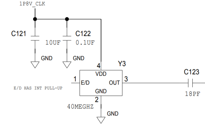
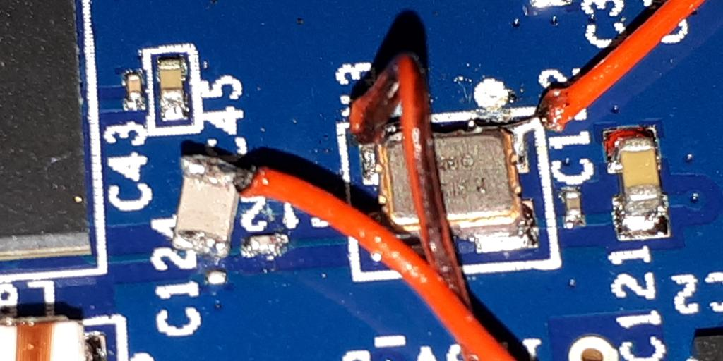
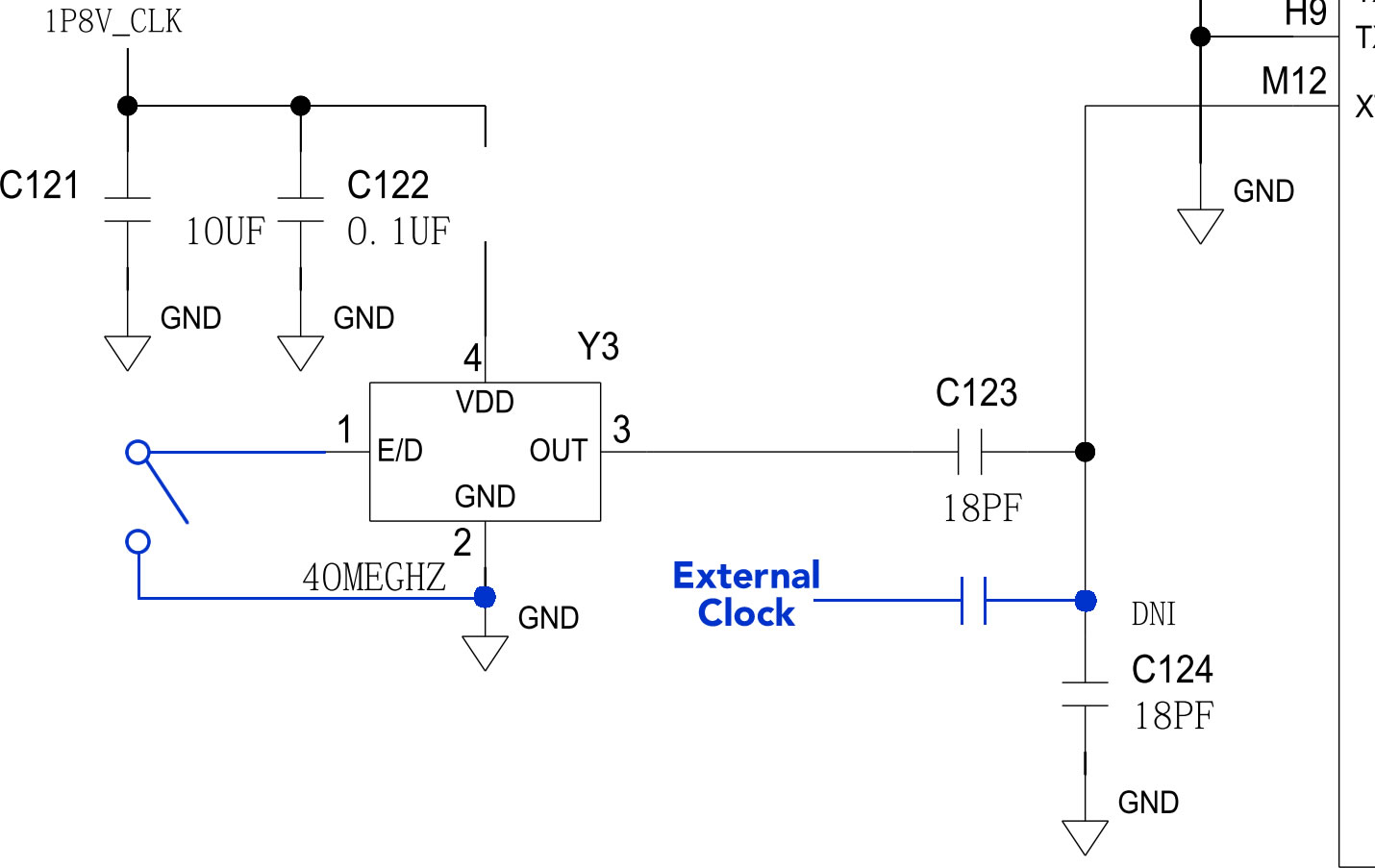
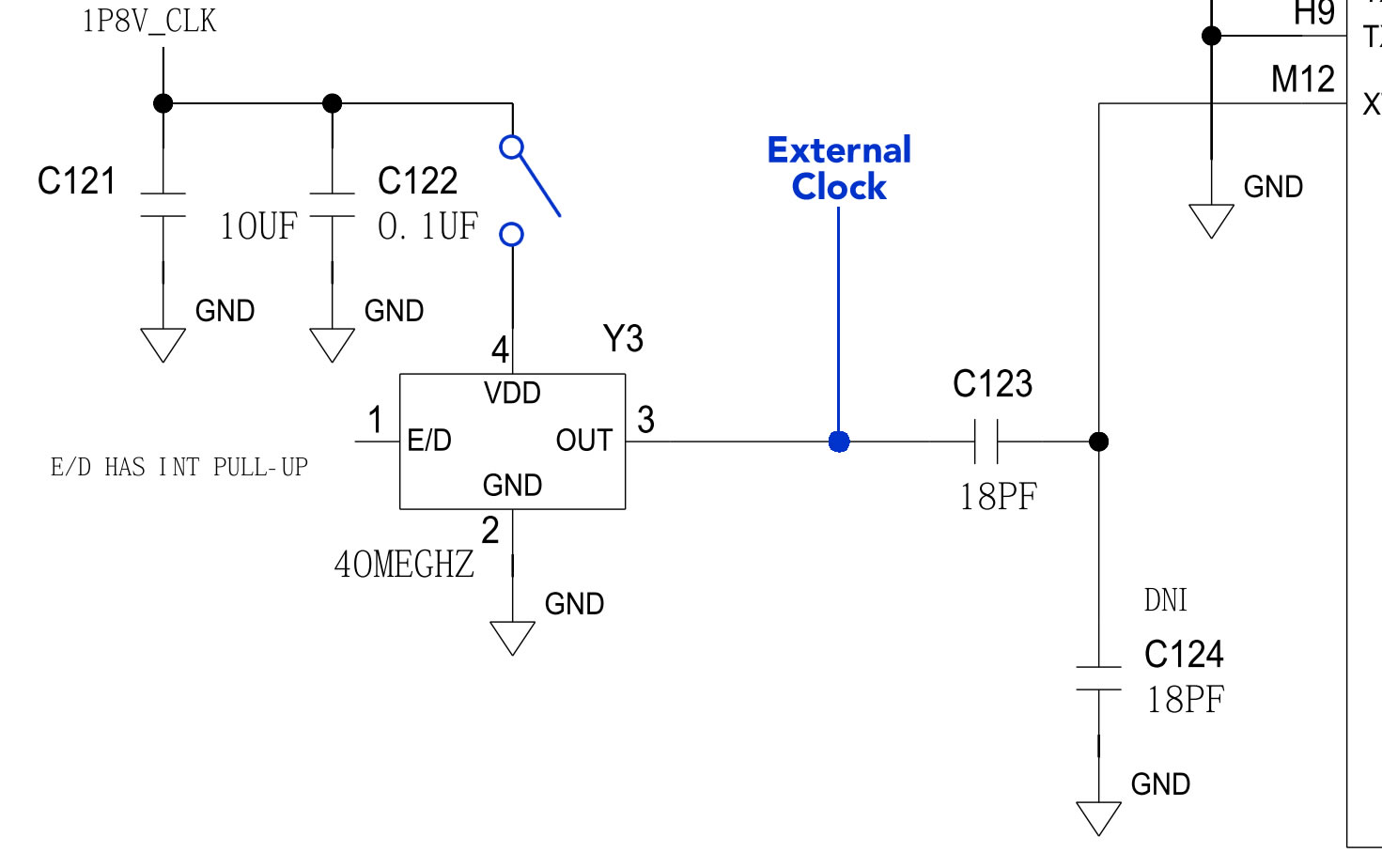
The existing TCXO has to be unsoldered and the external signal has to be brought in Pin 3, which has to be 1.8V peak-to-peak maximum. On the PlutoSDR board, C123/C124 as an AC divider to get things down to 1.3V p-p. The internal capacitance of the pin means we don’t actually need to stuff C124 to achieve this.
Another suggestion from F4DAV is to use pin 1 E/D (Enable/Disable) of the TCXO RAKON to enable or disable operation of the original TCXO. By setting Pin 1 to ground (GND), the TCXO RAKON is disabled.
Implementation by F4DAV
Original TCXO disable command for PlutoSDR
Program the new reference frequency and reboot your PlutoSDR
If your external reference or TCXO is not at 40MHz, but for example at 25MHz, you will need to indicate this change to the AD9363. To do so, connect to the Pluto (as described later in the paragraph Connection to the Pluto SDR by terminal in this article).
fw_setenv ad936x_ext_refclk "<25000000>"
fw_setenv xo_correction 25000000
pluto_reboot reset
To check if the changes have been taken into account, reconnect and launch the command
cat /proc/device-tree/clocks/clock@0/clock-frequency | xxd
That should bring you the line
# 00000000: 017d 7840 .}x@
The result is in hexadecimal. The hex value 017d7840 is indeed 25000000 decimal (check for example with this online converter), so our frequency has been applied.
Here are some references of GPSDO generators that can be used. However, I remind you that you must hold a maximum of 1.8Vp-p before C123. LeoBodnard’s programmable model, set to 36mA should give you 1.6Vdc on 50 ohms, so it is well adapted for that.
- Programmable GPSDO from LeoBodnard
- DF9NP GPSDO 10MHz
- With 3.3V output

EA3HMJ proposes to add a switch on the TCXO power supply to allow the choice of the internal (TCXO) or external (GPSDO) source. It is then necessary to unsolder the C122 bracket and to connect it to the switch. Pin 4 of the TCXO is then isolated and can be connected to the switch.
TCXO/GPSDO selector switch

Implementation of EA3HMJ
The Windows drivers
It will soon be time to connect the Adalm Pluto to the PC.
-
-
-
- Download and install the driver for Windows (https://wiki.analog.com/university/tools/pluto/drivers/windows or the file PlutoSDR-M2k-USB-Drivers.zip v0.7 file directly from this site).
- Now it’s time to connect the Adalm Pluto for the first time via its central USB socket directly to the computer. A disc drive will appear in your file explorer. It will be named PlutoSDR. LED1 is flashing slowly.
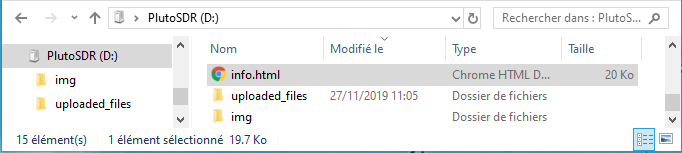
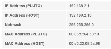
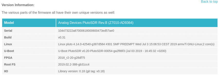
- Double-click on the info.html file. At the bottom of the page, you will find the IP address of your PlutoSDR connected to your USB port. The info.html page is also accessible through the IP address in your browser from the PC on which your Adalm Pluto is connected. Type in the URL of your browser, or click : http://192.168.2.1
-
-


Firmware update
- Download the file plutosdr-fw-v0.31.zip on https://github.com/analogdevicesinc/plutosdr-fw/releases/latest or directly on this website : plutosdr-fw-v0.31
- Extract the contents of the zip file.
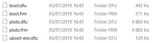
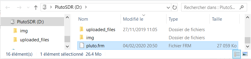
- Your Adalm Pluto is plugged in. Copy the file pluto.frm to the root of the PlutoSDR drive
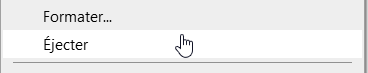
- To start programming the firmware, right-click on the PlutoSDR drive, and click Eject.

- After updating, the PlutoSDR drive reappears in your browser. You can launch your web browser and access the main page of the Adalm Pluto by http://192.168.2.1/


Extending the capabilities of Adalm Pluto
Increasing the frequency range
The current version of Pluto uses the AD9363 chip which is “limited” to a frequency range of 325 to 3800 MHz and a bandwidth of 20 MHz. However, the AD9364 chip, which can support a frequency range of 70 MHz to 6000 MHz and a bandwidth of 56 MHz, is claimed to be almost identical to the AD9363 chip. The Adalm Pluto can be tricked into seeing an AD9364 chip simply by changing a parameter variable, but there is no guarantee that the full range of frequencies and bandwidth will be given for all devices. It is possible that the AD9363 chips are actually AD9364 chips that have failed performance quality checks and have just been renamed to a low-end model, or that a cheaper semiconductor process is being used with the low-end chip.
Connection to Pluto SDR by terminal
On the computer on which your Adalm Pluto is connected, we will install terminal emulation software. I use and recommend Putty.
Connect with terminal software, indicating the IP address of the PlutoSDR, SSH protocol (port 22).
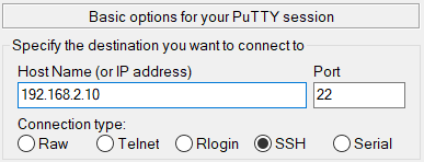

Enter the default login and password.
login : root
password : analog
Warning: Permanently added '192.168.2.1' (ECDSA) to the list of known hosts.
root@192.168.2.1's password: analog
Welcome to:
______ _       _        _________________
| ___ \ |     | |      /  ___|  _  \ ___ \
| |_/ / |_   _| |_ ___ \ `--.| | | | |_/ /
|  __/| | | | | __/ _ \ `--. \ | | |    /
| |   | | |_| | || (_) /\__/ / |/ /| |\ \
\_|   |_|\__,_|\__\___/\____/|___/ \_| \_|

v0.31
http://wiki.analog.com/university/tools/pluto
#
By default, the following two commands should return errors:
# fw_printenv attr_name
## Error: "attr_name" not defined
# fw_printenv attr_val
## Error: "attr_val" not defined
#
Pass the two commands and restart the pluto with the third line.
# fw_setenv attr_name compatible
# fw_setenv attr_val ad9364
# reboot
After rebooting and reconnecting to your PlutoSDR, both commands return the saved settings.
# fw_printenv attr_name
attr_name=compatible
# fw_printenv attr_val
attr_val=ad9364
#
Enabling the second processor core of the PlutoSDR
It’s not sure if it’s really useful, but maybe for the very large signals of a few mega-symbols ?
The following command returns the characteristics of the processor.
cat /proc/cpuinfo
Still connected with your terminal to the Adalm Pluto, run the command.
fw_setenv maxcpus
You can run the following command again, the result now shows both CPU cores.
# cat /proc/cpuinfo
processor       : 0
model name      : ARMv7 Processor rev 0 (v7l)
BogoMIPS        : 666.66
Features        : half thumb fastmult vfp edsp neon vfpv3 tls vfpd32
CPU implementer : 0x41
CPU architecture: 7
CPU variant     : 0x3
CPU part        : 0xc09
CPU revision    : 0

processor       : 1
model name      : ARMv7 Processor rev 0 (v7l)
BogoMIPS        : 666.66
Features        : half thumb fastmult vfp edsp neon vfpv3 tls vfpd32
CPU implementer : 0x41
CPU architecture: 7
CPU variant     : 0x3
CPU part        : 0xc09
CPU revision    : 0

Hardware        : Xilinx Zynq Platform
Revision        : 0003
Serial          : 0000000000000000
#
Evariste F5OEO has developed a whole series of SDR processing software. The first ones were dedicated to the LimeSDR transceiver. For the PlutoSDR, Evariste proposes directly a firmware to be installed on the equipment : PlutoDVB. The firmware integrates a DATV image transmitter, but also other possibilities: a narrowband SSB transmitter, a narrowband SSTV transmitter, a narrowband FREEDV digital modulator, and a modulator to draw images on the SDR waterfall.
I will develop here only the digital video modulator function of the firmware.
Download PlutoDVB F5OEO firmware
To date, Evariste has released several versions of firmware :
- The “stable” firmware version
- On the forum VivaDATV.org (Registration required on the forum dedicated to DATV and mini-DATV receivers – This is a mine of very useful information for the DATV, I urge you to register.)
- On the current site : pluto.frm.20191010.zip
- Le firmware “beta”
- On firmware.hackhamradio.com/pluto.frm
- On the current site : pluto 20191220-1058.zip
- The beta firmware “for the brave”.
- On firmware.hackhamradio.com/beta_for_the_brave/pluto.frm
- On the current site : pluto beta_for_the_brave 20200205-2104.zip
Like many others, I use the latest version called “for the brave”. It works well. The following explanations are based on this version.
Installing the firmware of Evariste F5OEO
- Download the frm file or unzip the contents of one of the zip files. The file pluto.frm is the firmware.
- Install the firmware by following the steps as described previously.
- After updating the firmware, the PlutoSDR drive reappears in your browser. You can launch your internet browser and access the main page of Pluto_DVB installed on the Adalm Pluto by http://192.168.2.1/


Accessing Pluto SDR remotely via network
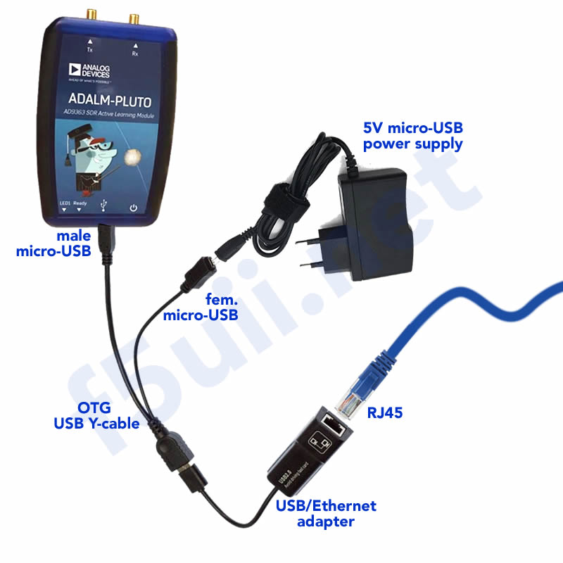
- USB / Ethernet adapter with a mini USB OTG Y cable – 100 MBit/s is sufficient
Normally your PlutoSDR, once connected as shown in the diagram on the right, should automatically have an IP address given by your network router (router, or internet box). In my case, this was not the case. For with a fixed IP address, which does not change, I therefore modified the file which is on in the root directory of the PlutoSDR drive in the config.txt file.
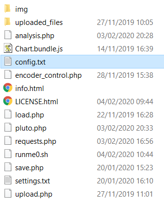

- Open the config.txt file
- After the line [USB_ETHERNET], change the IP address by entering a free IP address from your network. I advise you to use the IP Advanced Scanner which allows you to list all the devices connected on your network (and find your Adalm Pluto on the network, under the hostname pluto). Your Pluto will have this fixed IP address at the next reboot. In my case, the chosen address is 192.168.1.8. It will appear in the rest of the article, and you will of course replace it with the IP address you programmed.
Do not change the address of the NETWORK section but only the address of the USB_ETHERNET section.
ipaddr_eth = 192.168.1.8
# Analog Devices PlutoSDR Rev.B (Z7010-AD9363)
# Device Configuration File
#   1. Open with an Editor
#   2. Edit this file
#   3. Save this file on the device USB drive
#   4. Eject the device USB Drive
# Doc: https://wiki.analog.com/university/tools/pluto/users/customizing

[NETWORK]
hostname = pluto
ipaddr = 192.168.2.1
ipaddr_host = 192.168.2.10
netmask = 255.255.255.0

[WLAN]
ssid_wlan =
pwd_wlan =
ipaddr_wlan =

[USB_ETHERNET]
ipaddr_eth = 192.168.1.8
netmask_eth = 255.255.255.0
gateway_eth = 192.168.0.254

[SYSTEM]
xo_correction =
udc_handle_suspend = 0

[ACTIONS]
diagnostic_report = 0
dfu = 0
reset = 0
calibrate = 0
OBS Studio
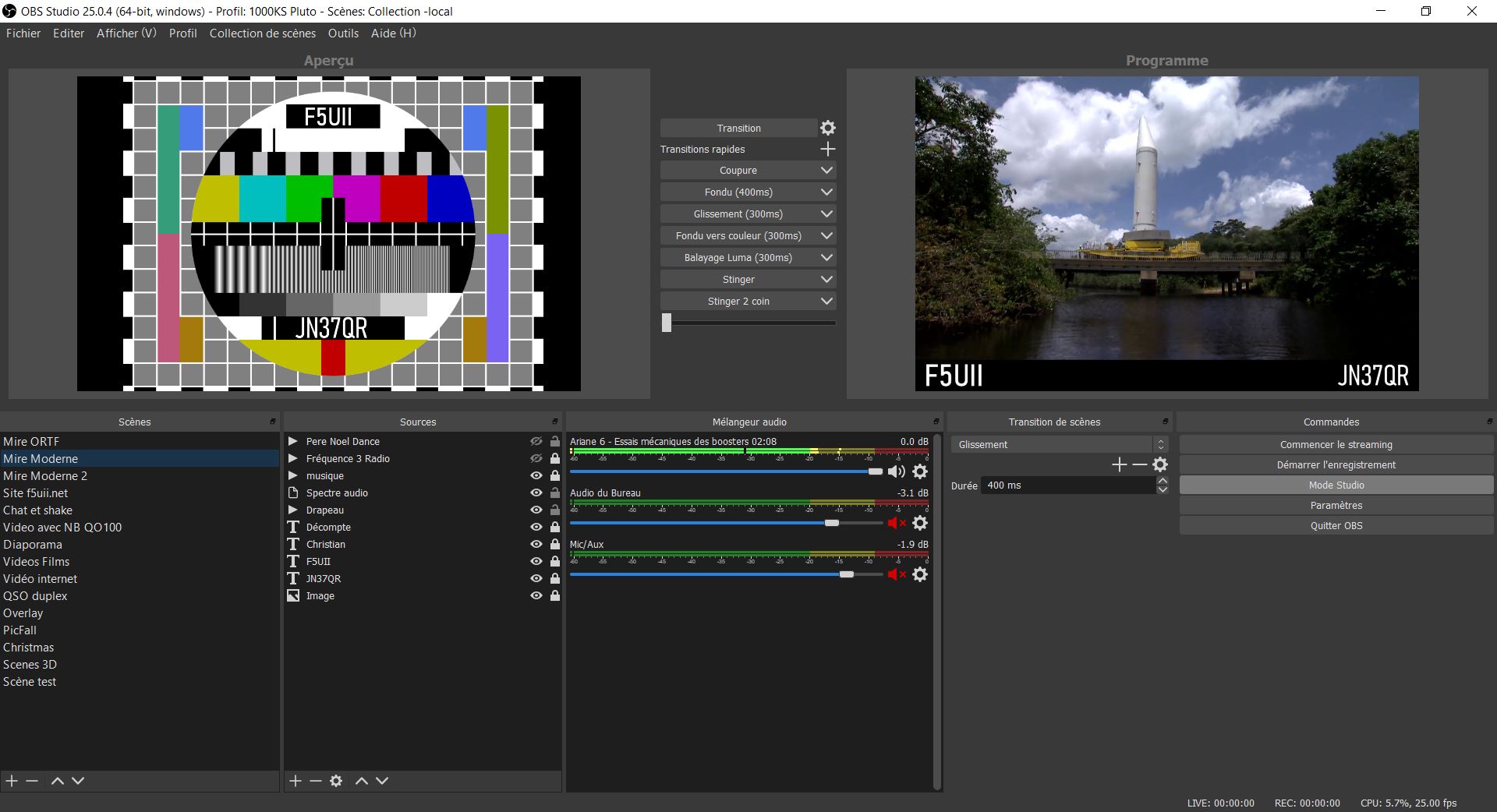
We need to send a video stream to the PlutoDVB integrated server. It is possible, for example, to stream an image directly from a smartphone with the Larix Broadcaster software. I don’t develop this support, but if you are interested, you can find an example of configuration on the PlutoDVB integrated help page (in the Phone section). It seems much more interesting to me to present the software I prefer to use to transmit my DATV images: OBS Studio.
OBS Studio (Open Broadcaster Software) is a free open source software that allows to compose video images, and to broadcast them to internet platforms like Youtube or twitch for example. It is often used by gamers who broadcast their game live.
This software is really flexible with an intuitive interface and allows you to compose your images, with multiple video sources (webcam, internet), audio, still images, scrolling texts… filters allow you to process, modify the video and audio, transitions allow you to switch from one composition (scenes such as the software calls them) to another. Plugins allow to add interesting functions. The only limit I see will be your inspiration.
Our first test pattern in OBS Studio
To familiarize ourselves with the software, and after having installed OBS Studio, we will build our first Scene, to broadcast a customized TV test pattern. Let’s see it step by step.
- Download and install OBS Studio
- Launch the software for the first time. Answer No to the Auto-configuration question. Your installation is initialized with a default profile, in which an empty scene is placed.
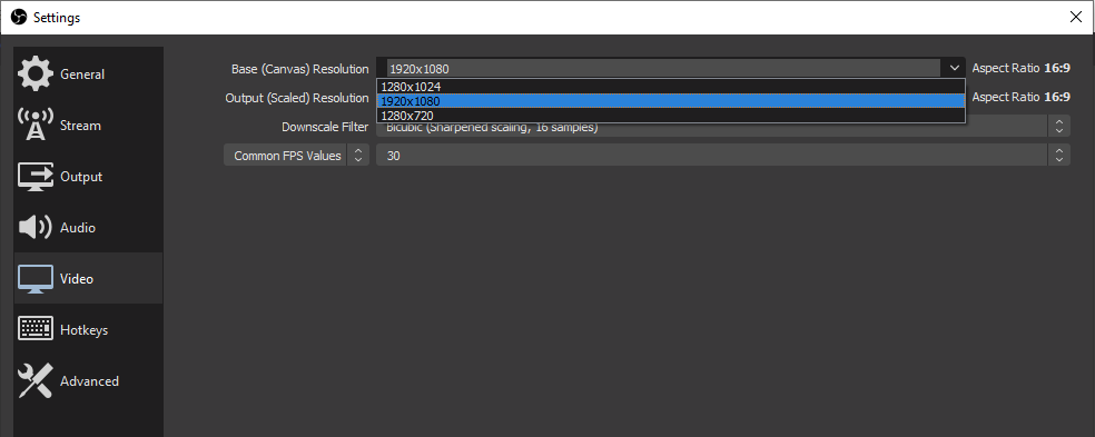
- The first thing to do is to adjust the definition of your broadcast screen. Click on the File / Settings menu. Go to the Video screen, and set your basic resolution, and output resolution (the same as above). Broadcasts and screens are now largely in 16:9 format. Validate by OK
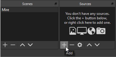
- We’re going to rename the first Scene to “Mire” (french for TV-Pattern) so that we’ll be able to find our way around when we have more Scenes added. Right click on the scene, choose Rename. I’m entering “Mire” (Pattern).
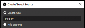
- Now let’s add an image to the Scene, by clicking on the plus sign and choosing the Image source.
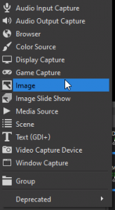
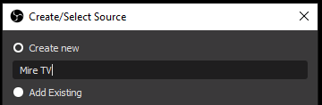
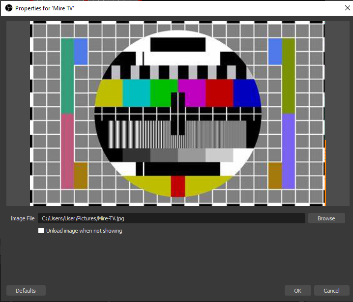
- Name your image “Mire TV”. Click OK
-
Select your image. You can download the file Mire-TV.jpg. Click OK.

- Using the red handles, resize the image to the width of the scene. When the final position is found, lock its position by clicking on the padlock of the TV test pattern source. This will avoid moving the image inadvertently afterwards.
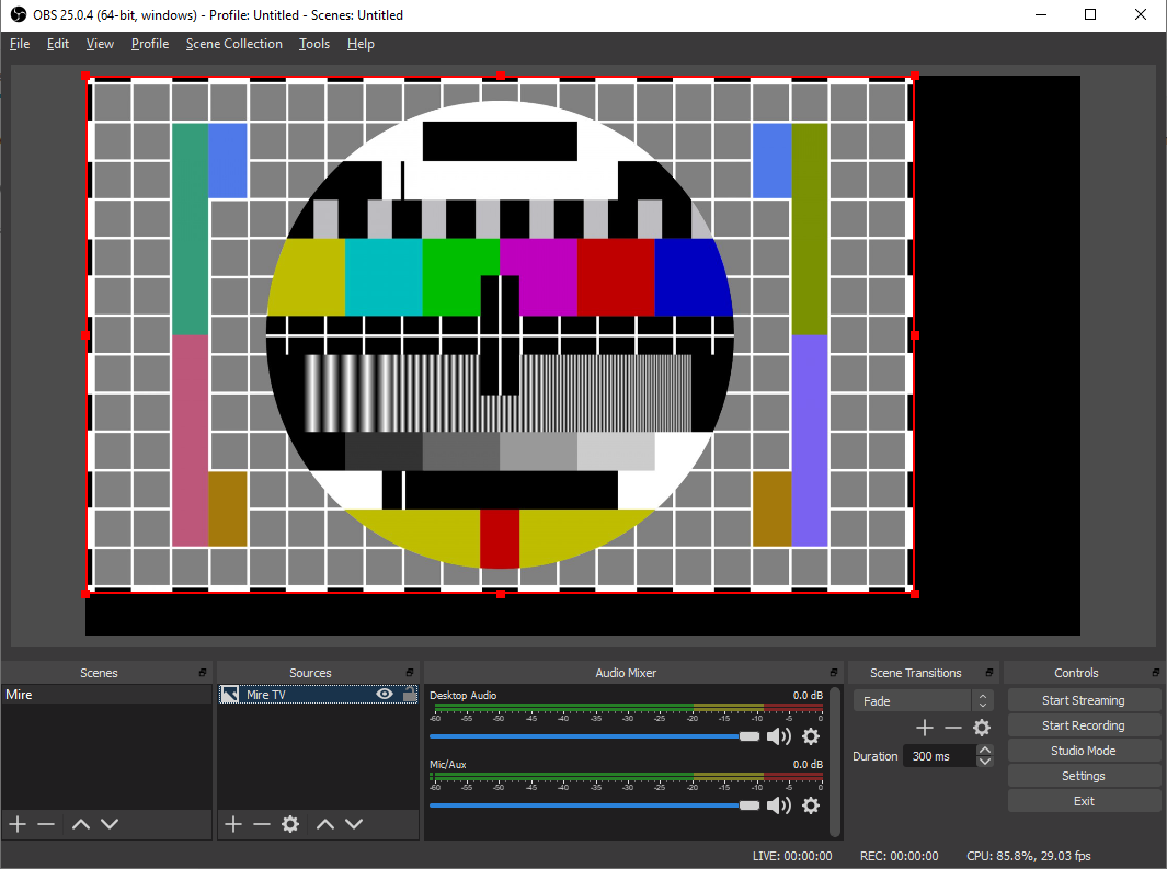
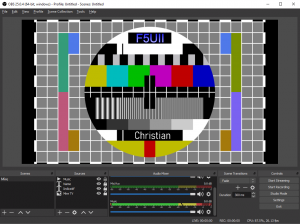
- We’re now going to add your call sign to the pattern. With a click on the plus, add a Text(GDI+) source. Proceed as in the first case, to name the source. In the properties window, you can define a font, the color of your choice. Enter your callsign in the Text field. Click OK. The text is added to your scene.
- Take care that in the list of sources, your text is well listed above the background image. Indeed, the order of the sources defines the overlay layers in the scene. Resize your text.
- We still have to add sound to the pattern. You will now choose a Media source, and name it Background Music for example. Accepted audio formats are mp3, acc, ogg and wav. In the properties of the source, remember to check Loop so that the music keeps restarting. I invite you to check the license conditions of your audio sources before integrating them into your broadcasts. Here are a few platforms that you can use to find your music.
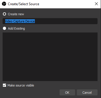
- Following the same principle, you add another composition, another scene, for example to integrate a webcam connected to your PC :
- Click on the + at the bottom of the Scenes column. Give a name to the new Scene
- Click on the + at the bottom of the Sources column. Choose “Video capture device”, then choose your connected video source
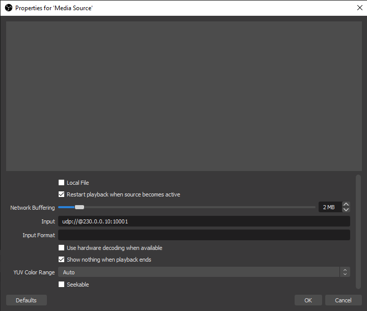
- You can also integrate in the scene a network image source (Media Source), for example the one of the broadcast made by your DATV reception (Minitiouner for example). Uncheck Local file, and enter the source IP address for example udp://@230.0.0.10:10001. You can also use a smartphone equipped with a camera to stream your video. Under Android, I use the software Droidcam or IP Webcam.
- I invite you to switch to the “Studio Mode” view (via the bottom right control button).On the right is displayed the image sent (streamed), and on the left, the scene you are ready to send.
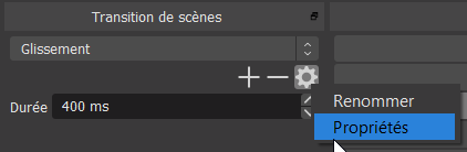
- To switch from one scene to another, select the scene to be transmitted, then click on one of the “Transition” buttons positioned between the two images. You will choose one of the available transitions (Cut, fade, scan …). The transitions are configurable in duration and rendering with the Scene Transitions / Priorities panel, or by adding a transition with the + button.


Now that we have some matter to broadcast, let’s see the settings expected by the Adalm Pluto and PlutoDVB. It integrates an RTMP server (Real-Time Messaging Protocol) which will receive the video stream sent by OBS Studio. It is mainly this server and the very simple way to broadcast the stream to the PlutoDVB that makes all its interest. The easy implementation of Evariste F5OEO’s firmware lies in the simplicity of a “line of parameters” sent from OBS to the Adalm Pluto. Let us see that in detail.
Video stream generation
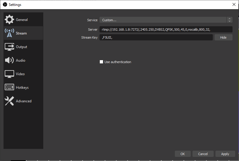
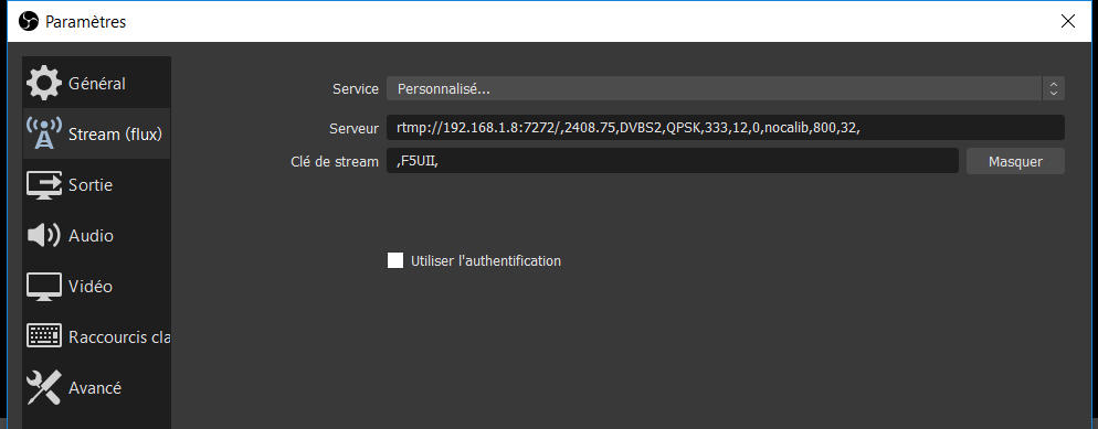
- In the OBS settings (File/Settings), we will indicate the destination of PlutoSDR: In the Stream tab, choose the “Custom…” service.
- In the field “Stream key”, in the second line, indicate your callsign with 2 commas. In the first line Server, the RTMP server integrated in the Adalm Pluto will be indicated, as well as all the characteristics of the DATV transmission. Be careful not to forget one of the separating commas. Here is an example.
- Now let’s detail the parameters that constitute the line.
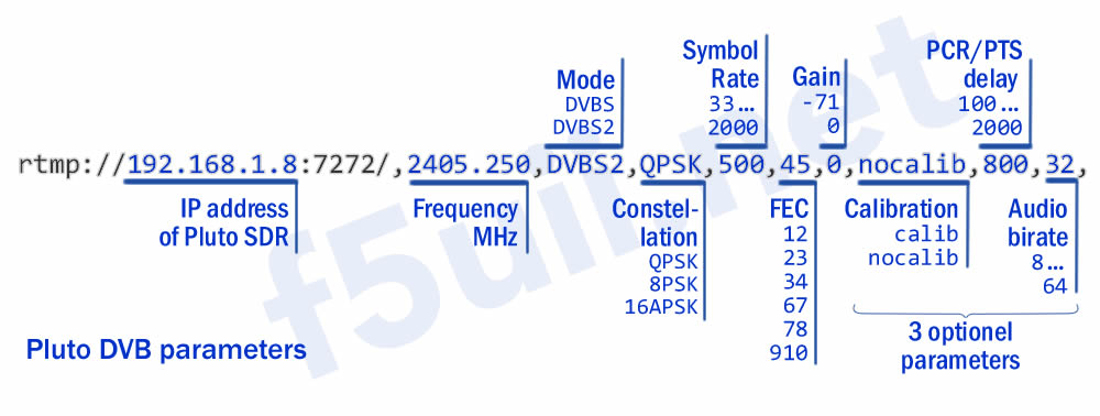

- The IP address is that of your Pluto. Connected in USB it is 192.168.2.1. If your Pluto is connected to the network, this is of course the IP address of your PlutoSDR on the network. Port 7272 is the default value to be used to transmit the video stream.
- The transmission frequency must be chosen in correlation with the bandwidth map of the Qatar Oscar 100 satellite’s wideband transponder and depends on the spectrum occupation and the Symbol Rate width you will be using. On the webSDR of the BATC eshail.batc.org.uk/wb a free channel is chosen and priority is given to the free narrowband portion. Refer to the rules specified in the chapter ‘QO-100 wideband operating guidelines and bandplan‘.
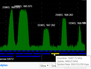
Select a free frequency
- The mode (usually DVB-S2).
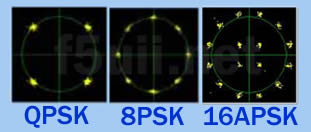
- The phase modulation constellation. For DVBS mode, only the QPSK constellation is possible.
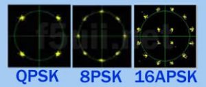
- The SR is the symbol rate of the transmission. The SR is the main variable that determines the frequency bandwidth of your signal. Pluto DVB accepts from 33 to 2000 kS.
- FEC stands for Forward Correction Error. The FEC is a data ratio between the useful data (image, sound) and the data added to the transmission, which are used to a certain extent and according to the criteria of plausibility, to correct errors during decoding, errors caused by the hazards of the transmission. At the time of transmission, data are introduced which enable the receiver to reconstitute the useful information which would have been lost. The FEC can thus take values such as 14 for 1/4, 13=1/3, 25=2/5, 12=1/2, 35=3/5, 23=2/3, 34=3/4, 45=4/5, 56=5/6, 89=8/9, 910=9/10. This is the number of useful bits for the number of transmitted bits, for example: 3/5 corresponds to 3 useful bits for 5 transmitted bits, i.e. 2 used for correction.
- Gain is expressed in dBm, the maximum transmit signal is reached by setting the value to 0.
- The emission calibration (a maximum amplitude peak) can be generated with the calib value. (first of the optional parameters – not tested by me)
- The PCR/PTS delay can be increased if the encoding suffers from a lack of bitrate. We will come back to this in more detail. (optional parameter)
- The audio streaming rate can be limited by PlutoDVB (optional parameter). OBS Studio can only broadcast a minimum of 64 kbit/s of audio. It can therefore be interesting to switch to 32kbit/s and to make the video or correction stream benefit from this increased rate.

TS stream to PlutoDVB – Video bitrate
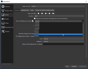
We will now tell OBS Studio the data rate we will send to PlutoDVB (the TS, Transport Stream), the definition of the transmitted image, and the compression encoding of the video stream.
Video bit rate
We will fill the TS (Video Transport Channel – Transport Stream) at a “Fixed Sample Rate” (CBR Constant Bit Rate). The CBR is calculated and depends on the mode (DVB_S, DVB_S2), the chosen constellation (QPSK, 8PSK…), the chosen symbol rate (which itself with the rolloff coefficient, defines the RF bandwidth occupied by your signal).
Calculators are available for calculating the flow rate. I quote here two online flow rate calculators.
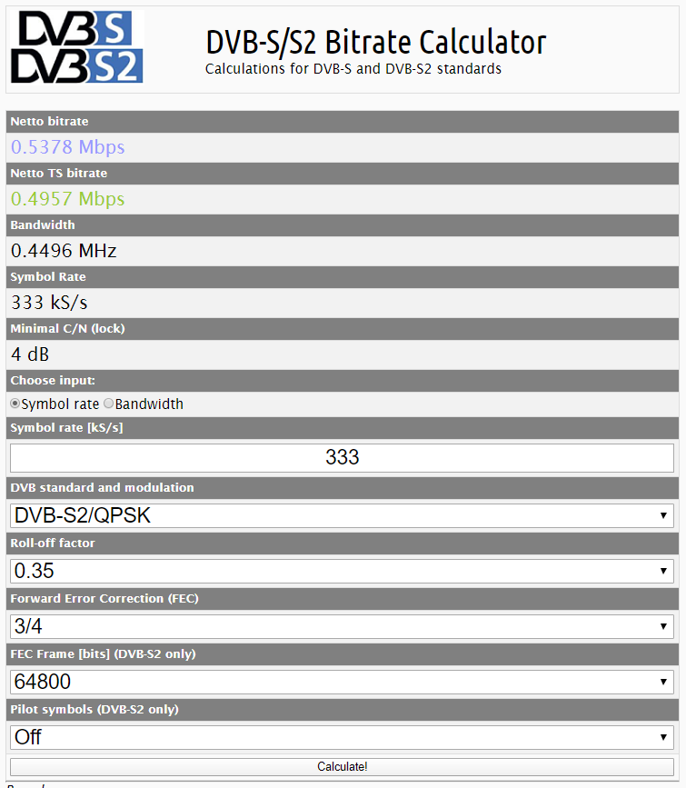
Calculation on Satbroadcasts.com
- On Roks-tv.com
- On Satbroadcasts.com
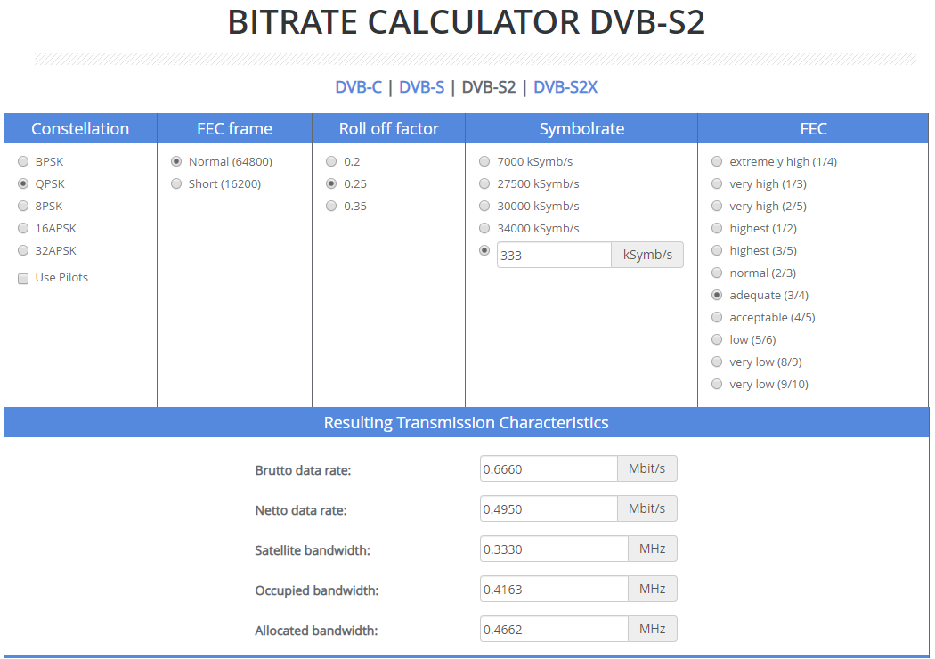
Calculation on roks-tv.com
For a “classic” DVB-S2 /QPSK transmission, in these tools, choose the constellation (QPSK), indicate that it is DVB-S2, and enter your choice of SymbolRate “width” (333 for example), and choose the FEC. This gives you the Netto TS bitrate value (Netto TS bitrate, or Netto data rate).
This total net bit rate value includes video, audio and also some other DVB “control” data (PMT – Program Map Table, PAT – Program Association Table, SDT – Service Description Table). Of course the largest data is of course the video itself.
To determine the video bit rate (VBR), we take between 60 and 70% of the net bit rate. The most important first step is that the bit rate is not too high. In the following table, you will find in the CBR column, the video bitrate values that I use myself (with the PTR/PTS delay buffer of 800, the default value used by PlutoDVB, and with forcing the audio bitrate to 32 kbps last parameter of the Stream line).
The table gives you the bit rates for a DVB-S2 signal in QPSK. The following pages of the table show the upper SRs.
FEC SymbolRate (kS/s) Brut data rate Netto data rate OBS CBR (kbps) Mini MER RX
extremely high (1/4) 125 250 61 -2.35
very high (1/3) 125 250 81 -1.24
very high (2/5) 125 250 98 -0.3
highest (1/2) 125 250 123 1
highest (3/5) 125 250 148 2.23
normal (2/3) 125 250 166 3.1
adequate (3/4) 125 250 185 4.03
acceptable (4/5) 125 250 198 72 4.68
low (5/6) 125 250 206 78 5.18
very low (8/9) 125 250 221 90 6.2
very low (9/10) 125 250 223 95 6.42
extremely high (1/4) 250 500 122 -2.35
very high (1/3) 250 500 162 -1.24
very high (2/5) 250 500 197 -0.3
highest (1/2) 250 500 247 1
highest (3/5) 250 500 297 2.23
normal (2/3) 250 500 332 3.1
adequate (3/4) 250 500 371 4.03
acceptable (4/5) 250 500 396 4.68
low (5/6) 250 500 412 280 5.18
very low (8/9) 250 500 442 6.2
very low (9/10) 250 500 447 6.42
extremely high (1/4) 333 666 163 -2.35
very high (1/3) 333 666 216 -1.24
very high (2/5) 333 666 262 -0.3
highest (1/2) 333 666 329 210 1
highest (3/5) 333 666 395 270 2.23
normal (2/3) 333 666 442 320 3.1
adequate (3/4) 333 666 495 380 4.03
acceptable (4/5) 333 666 528 410 4.68
low (5/6) 333 666 548 430 5.18
very low (8/9) 333 666 588 465 6.2
very low (9/10) 333 666 595 470 6.42
extremely high (1/4) 500 1000 245 -2.35
very high (1/3) 500 1000 324 210 -1.24
very high (2/5) 500 1000 394 270 -0.3
highest (1/2) 500 1000 494 370 1
highest (3/5) 500 1000 594 475 2.23
normal (2/3) 500 1000 664 540 3.1
adequate (3/4) 500 1000 743 620 4.03
acceptable (4/5) 500 1000 793 665 4.68
low (5/6) 500 1000 824 700 5.18
very low (8/9) 500 1000 884 760 6.2
very low (9/10) 500 1000 894 6.42
extremely high (1/4) 1000 2000 490 370 -2.35
very high (1/3) 1000 2000 649 530 -1.24
very high (2/5) 1000 2000 789 650 -0.3
highest (1/2) 1000 2000 988 830 1
highest (3/5) 1000 2000 1188 1030 2.23
normal (2/3) 1000 2000 1328 1140 3.1
adequate (3/4) 1000 2000 1487 1310 4.03
acceptable (4/5) 1000 2000 1587 4.68
low (5/6) 1000 2000 1648 5.18
very low (8/9) 1000 2000 1768 6.2
very low (9/10) 1000 2000 1788 6.42

Let’s report this CBR value in OBS Studio :
- Open the Settings panel (from the File menu, or directly from the command button, at the bottom right of the screen)
- Select the second line “Stream”
- Choose Service “Custom…”Enter the stream command line in the Stream tab to transmit to the satellite.
-
rtmp://192.168.1.8:7272/,2408.25,DVBS2,QPSK,333,12,0,nocalib,800,32,
and the stream key with your callsign enclosed in commas
,F5UII,
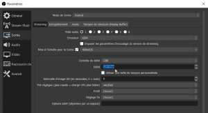
- Select the third line “Output”.
- We switch to the output mode to Avanced.
- Select the Streaming tab. We will enter the CBR rate
- Validate these settings by clicking on OK in the Settings window.
- We can switch to the transmit by clicking on the Start streaming command button. To make your first tests, I advise you not to transmit to QO100. After a few seconds, the transmission signal is effective. Note that the same button allows you to stop the transmission.
- If the Adalm Pluto is receiving the stream, in the bottom right corner of the OBS Studio window the green light appears.


![]()

On this video, you can compare the two situations.
- On the left a setting of too high a video bit rate. The red dots that appear are information that cannot be processed by PlutoDVB. On reception, the audio signal will show white spots or cuts, the video will be jerky or frozen.
- On the right, a correct data rate, all the points of the buffered data curve are green. Even if, depending on the movement of the curve over time, they approach the horizontal axis at 0, but at no time does the curve pass below the axis. It can also be seen in the data type decomposition graph (transport stream analysis, top) that data packets are null present. This indicates that we might be able to increase the CBR throughput a bit. (Based on the minimum null packet stub, maybe 5 or 10kpbs for this illustration . To be tested by a new iteration of tuning, detailed below).
To refine the CBR video bit rate, I recommend the following technique:
- Calculate your flow rate (or let the rate calculated with online tools as indicated above) using a rather low coefficient (60%).
- Switch to streaming your channel. You are asked not to transmit to the satellite during this tuning phase and to make your settings on a load or another frequency. Personally, my final amplification stage is disabled.
- Consult the dynamic graph of analysis of the PlutoDVB video buffer. On the Transport stream analysis graph, the number of null packets are as many kbit/s that you will be able to add (transfer) to the value of your CBR, to make it useful video data. Turn off your streaming.
- Readjust (increase) your CBR in OBS Studio with the null packet number. Resend your stream to PlutoSDR.
- The null packages must have decreased. You should always have some, to compensate for the vagaries of some videos with highly fluctuating streams, and which is necessary to compensate for the “time constant” of the stream’s arrival at Adalm Pluto.
Depending on the dynamics of your video images, you may notice a larger amplitude of buffer variation. If this is the case and the signal passes under the horizontal axis from time to time but returns to a steady state in the green zone, you can increase the PCR/PTS (buffer) value (1000 – 1500 for example). The disadvantage is the longer transmission delay.
The choice of the FEC
Before seeing how to choose the right FEC, it is necessary to introduce the notion of MER.
MER (Modulation Error Rate)
The modulation error rate or MER is a measure used to quantify the performance of a digital radio (or digital television) transmitter or receiver in a communication system using digital modulation (such as PSK modulation). A signal sent by an ideal transmitter or received by a receiver would have all points of the constellation precisely at the ideal locations, however various imperfections alter the constellation in implementation (such as noise, low image rejection rate, phase noise, carrier suppression, distortion, etc.).
MER can be considered as an indicator of signal strength at reception. If your transmit signal is lowered by 3 dB, you will see a decrease of approximately 3 dB MER at reception. The minimum reception levels (minimum MER) are dependent on the transmitter’s FEC :

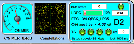
MER de 6.4dB pour un minimum requis de 4dB (FEC3/4)
You will only be able to decode images at a given MER level if you choose a FEC that does not require more signal. For example, for a signal with an FEC of 3/4, (3 useful data + 1 error correction data), your signal will be decoded only if the MER level is 4.2 dB. Refer to the right column of the table above.
- FEC 1/2 : 1.7 dB
- FEC 2/3 : 3.3 dB
- FEC 3/4 : 4.2 dB
- FEC 5/6 : 5.1 dB
- FEC 6/7 : 5.5 dB
- FEC 7/8 : 5.8 dB
Necessary signal power and width
For a 250 KS signal on a 1.2m dish, it is common to indicate that you need 30W. By doubling the size of your dish, you will divide the power needed by 4. In the table below you can see how the power needed for a 250KS signal evolves according to the diameter of the dish.
| Dish diameter (cm) | Power (W) | Power (dBm) |
|---|---|---|
| 60 | 120 | 50.8 |
| 80 | 67 | 48.3 |
| 90 | 53 | 47.2 |
| 100 | 43 | 46.3 |
| 120 | 30 | 44.8 |
| 150 | 19 | 42.8 |
| 180 | 13 | 41.1 |
| 200 | 11 | 40.4 |
| 240 | 7.5 | 38.4 |
But also, according to the transmitted spectrum width, you will multiply the necessary power by the coefficient indicated in the following table to know the necessary power. For example, you can transmit a 125 KS signal and a 1.2m parabola by going to half power, i.e. 15W. You will find the same signal level, just by transmitting less data via the satellite.
| SR (kSymbol) | Factor |
|---|---|
| 2000 | 8.00 |
| 1500 | 6.00 |
| 1000 | 4.00 |
| 500 | 2.00 |
| 333 | 1.33 |
| 250 | 1.00 |
| 125 | 0.50 |
| 66 | 0.26 |
| 33 | 0.13 |
The image definition is the size of the image, the video you are going to transmit. You will choose the definition according to your CBR video bit rate. You will easily understand that it is not possible to transmit a large fluid image without blurring or artifacts at a low bit rate. H.264 compression is generally available as standard on PCs and graphics cards;

Set your definition and the H.264 encoder in the OBS Studio parameters, in the Encoder fields (x264 or other proposed h264 encoder, depending on your graphics card) and output scaling.
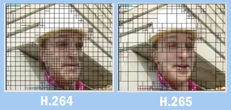
There is also the H.265 encoding with a much more powerful compression, and capable of being sent to PlutoDVB. Thanks to an algorithm that increases the static areas in the image and “tightens” the compression mesh, the H.265 encoder is able to save up to 70-80% of bandwidth for the same quality as H.264 encoding.
On the other hand, H.265 encoding is only available on some recent graphics cards. Some third-generation Nvidia cards integrate an NVENC H.265 encoder (NVIDIA’s encoder). Refer to the GPU manufacturer’s list to know if your GPU integrates this H.265 encoding technology.
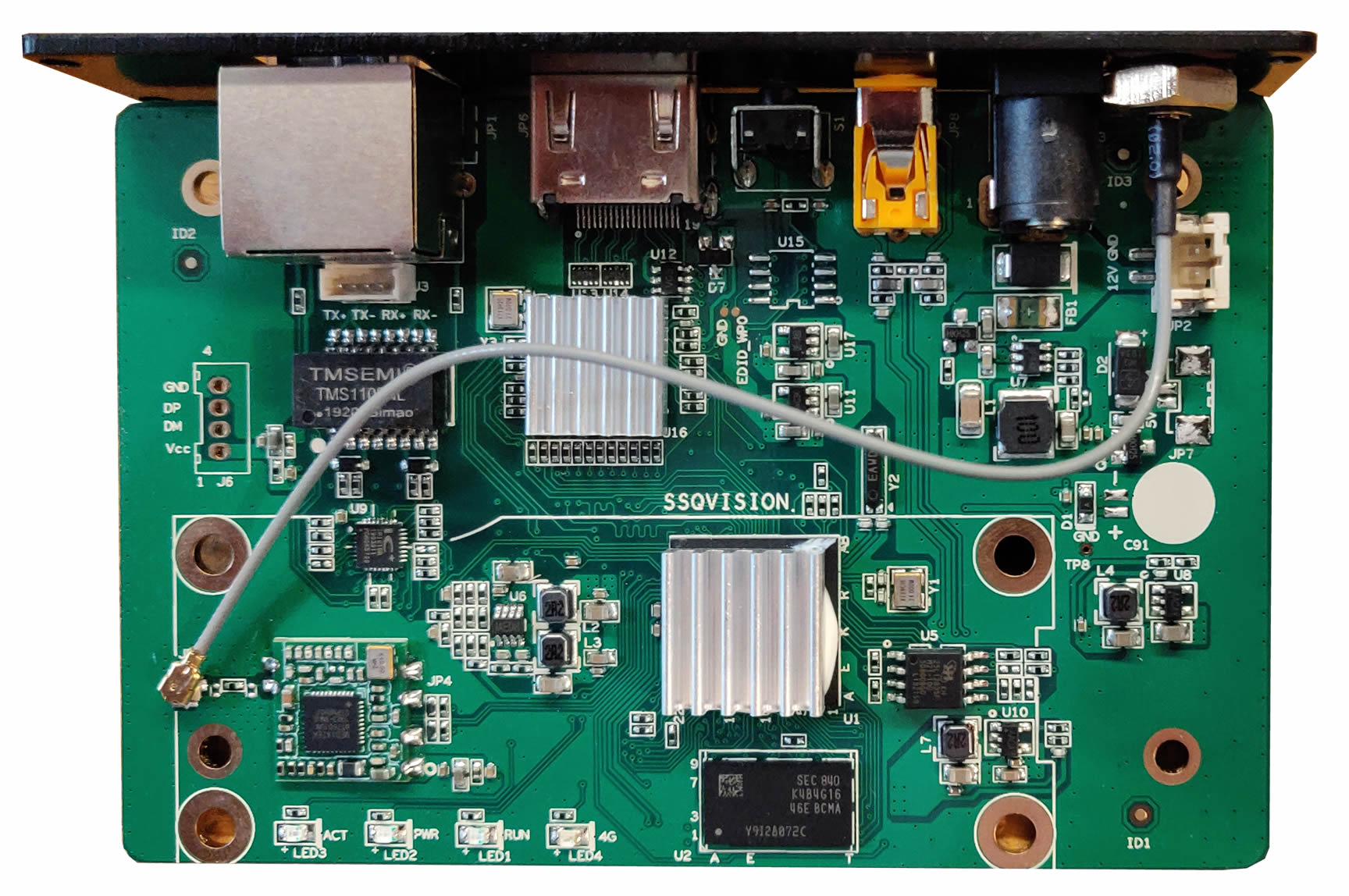
The external h.265 video encoder
For those who do not have a PC with a graphics card that supports H.265 encoding, there is the possibility of using an external encoder such as this one, referenced ON-DMI-16D (1080P@50fps) or ON-DM1-16A (1080p@60fps):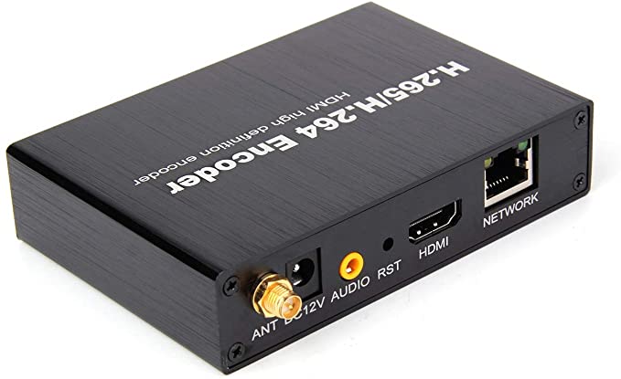
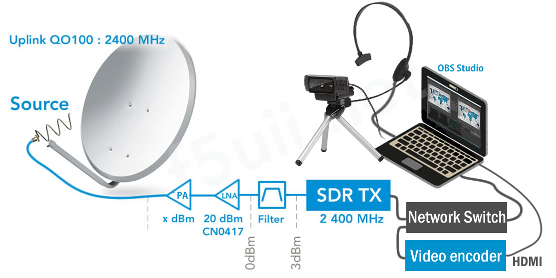
Synoptic with the video encoder on the network
The box is to be considered as a video projector that would be connected to your computer. Except that in our case, the encoder does not project an image but encodes the video and audio to send it via network to a receiver/diffuser, receiver which in our case is the Adalm Pluto with the firmware PlutoDVB. The H.264/H.265 encoder has an HDMI connector through which we will send the video and audio. It is advisable to use the RJ45 cable to connect the box to the network rather to the wifi network, which is more prone to disturbance.
You will find this H.264 and H.265 encoder at an interesting price distributed by the Chinese market :
Here is the H265 encoder manual : H.265 HDMI Video Encoder Quick Start Guide_ERV1.2.pdf
A complete article about the implementation of this external encoder with the Pluto (Brave version) is available on this blog : DATV: How to encode in h.265 with an external HDMI encoder
Note that Evariste is currently (May 2020) at work to reduce encoding delays, and make the stream more compliant with DVB-S2, DVB-S standards (See @f5oeo’s tweet on this subject). We are always looking forward with eager anticipation to the delivery of all its developments .
This page is the official rules established for satellite QO-100 broadband transponder usage, March 2020 edition. See the BATC website for the current version.
Due to the very large number of potential users, all transmitting stations should monitor the wideband spectrum monitor and the co-ordination chat window that has been established by AMSAT-DL and the BATC at https://eshail.batc.org.uk/wb/
Transponder Usage
As a general principle, the transponder should be only be used for short-duration tests and contacts. The only long-duration (more than 10 minute) transmissions should be:
- The TV beacon channel uplinked from Qatar or Bochum.
- Video of the live proceedings of AMSAT and Amateur TV Lectures and Conferences of wide interest. Examples might include:
- National AMSAT Conferences
- National Amateur TV Conventions
The following content is unacceptable:
- Recordings of events, or broadcast of events, not explicitly concerned with Amateur Satellites or Amateur TV
- Transmission of any copyright material (such as movies or TV channels)
- Repeated transmission of test videos unless essential for equipment alignment
The relaying of terrestrial Amateur TV Repeaters is discouraged unless the content is of exceptional amateur radio interest.
Transmission Power
All uplink transmissions should use the minimum power possible. QPSK transmissions should have a downlink signal with at least 1 dB lower power density than the Beacon – the web-based spectrum monitor enables users to set their uplink power to achieve this. Transmissions with symbol rates of less than 333 kS using 8PSK, 16 APSK or 32 APSK should use the minimum power density required to achieve successful reception.
Transmission Modes
Transmissions should use DVB-S2 where possible. For normal standard definition transmissions, 2 MS is the maximum symbol rate that should routinely be used.
To enable easy decoding the following DVB PIDs are recommended: Video 256, Audio, 257, PMT 32 or 4095, PCR 256 or 258. Service Name should be set to CallSign. PMT PIDs 4000 – 4010 should not be used.
On Wednesdays (UTC time), experimenters are encouraged to try other modes – perhaps 6 MS using the whole transponder for brief (less than 10 minute) periods. It is essential that users announce their plans on the chat room page, and always monitor it.
Experiments using unusual modes (for example ranging) should use the lower 1.5 MHz of the “Wide and Narrow DATV” Segment.
Beacon
The beacon transmits continuously (10491.5 MHz, DVB-S2, SR 1500 kS) to provide a test signal and to allow new users to precisely align their antennas.
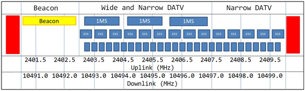
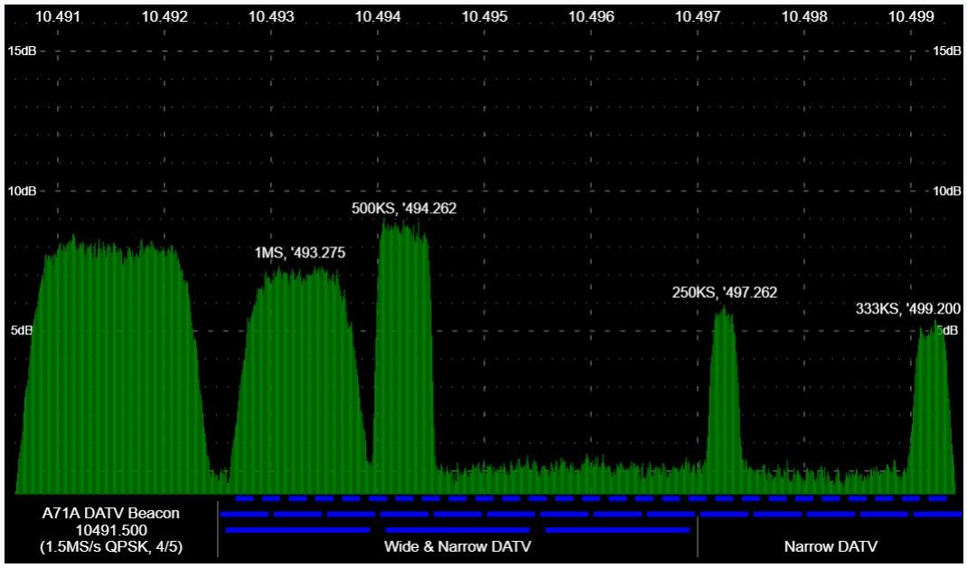
Bandplan
QO-100 Es’hail-2 Wideband Spectrum Monitor
- Narrow DATV transmissions should be confined to the “Narrow DATV” section, but may use the “Wide and Narrow DATV” section if the Narrow DATV section is fully occupied.
- A maintenance uplink occupying 10494.0 MHz – 10497.0 MHz will be used very occasionally; users are requested to give it absolute priority when notified.
- Recommended spot frequencies for various usages and symbol rates are listed below.
| Mode | Symbol Rate | Uplink Freq MHz | Downlink Freq
MHz |
Notes |
| Beacon | 1500 kS | 2402.0 | 10491.5 | Beacon DVB-S2 FEC 4/5 |
| Wide | 1 MS | 2403.75 | 10493.25 | 1.5 MS and 2 MS transmission should use this part of the band |
| Wide | 1 MS | 2405.25 | 10494.75 | |
| Wide | 1 MS | 2406.75 | 10496.25 | |
| Narrow | 333 kS | 2403.25 | 10492.75 | Use these 14 frequencies for
500 kS, 333 kS and 250 kS
Use frequencies above 10497.0 first |
| Then every 500 kHz until | ||||
| Narrow | 333 kS | 2409.75 | 10499.25 | |
| Very Narrow | 125 kS | 2403.25 | 10492.75 | Use these 27 frequencies for
125 kS, 66 kS and 33 kS
Use frequencies above 10497.0 first |
| Then every 250 kHz until | ||||
| Very Narrow | 125 kS | 2409.75 | 10499.25 | |
- Uplink 2401.0 – 2410.0 MHz RHCP, Downlink 10490.5 – 10499.5 MHz Horizontal.