
Intro
Following my previous article on the reception of Qatar Oscar 100 satellite signals, here is an article that is intended to be a way to complete your station, this time adding the transmission way. The objective is to describe a station that operates, as for reception, the SDR Console software. Far from conventional frequency converter solutions, SDR transmission has the advantage from its “small size”. However, we will look in detail at the possibilities of amplifying signals useful for upwards 2400 MHz.
It is important to remember that radio transmission is regulated at the international and national levels and that only amateur radio licence holders of Class 1 and Class 2 are authorised to transmit on the allocated frequency bands.
This article is “multi-page”, to be browsed from one page to another or directly from the contents to the desired page.
The amateur radio transponders of the satellite
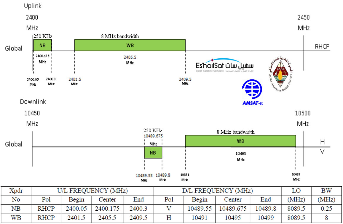
QO-100 fréquences de montées et descentes
The satellite offers two transponders for amateur radio amateurs :
- A transponder for narrow-band modes (NB: Narrow band)
- A transponder for wideband television transmission (WB: Wide band)
If you would like more information about satellite, I invite you to read the introduction to my article dedicated to reception. The table below specifies the descent and ascent frequencies on which we will transmit to be retransmitted by the transponders. You notice that unlike the two bands in descent, the polarization of the rising signals is in right circular polarization (RHCP) for both transponders, wideband (for digital television) and narrowband (for signals of 2.7kHz maximum).
| POLARISATION | Start (MHZ) | End (MHZ) | Width (MHZ) |
|---|---|---|---|
| Vertical (NB) | 10489,550 | 10489,800 | 0,250 |
| Horizontal (WB) | 10491,000 | 10499,000 | 8,000 |
| POLARISATION | Start (MHZ) | End(MHZ) | Width (MHZ) |
|---|---|---|---|
| RHCP (NB) | 2 400,050 | 2 400,300 | 0,250 |
| RHCP (WB) | 2 401,500 | 2 409,500 | 8,000 |
Synoptic of the transmission line
This is the basic principle of transmission on the uplink to the satellite, in SDR transmission. In this article we will discuss all the stages that make up the transmission line, and especially the transmission and amplification part: the transmitter is no more constituted by a “classical” conversion and analog technology but by a SDR (Software Defined Radio) technology emitter. To get a technical understanding of SDR, I suggest you watch the video presentation (in french) of a SDR conference by Sylvain F4GKR and available on the REF-Info channel.
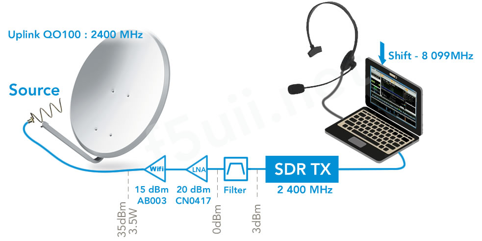
Synoptic of the transmission line to the Qatar Oscar 100 satellite – The CN0417 already includes a 2400MHz filter
This synoptic is composed of three main parts (from left to right):
- A transmitting antenna adapted to the 2.4GHz frequency
- An amplification and preamplification and filtering part
- The SDR transmitter capable of emitting on 2400MHz, operated by a computer equipped with SDR Console (installed on a Windows® system) and a sound card and headset
The 2400 MHz transmitting antenna
Several possibilities are available to you in regards to antennas:
- (instead of a parabola) a long right-polarized helix.
- 45 helix turn RHCP (16dB)
- This antenna can be built by itself according to the principle described below.
- a dish with at its focus
-
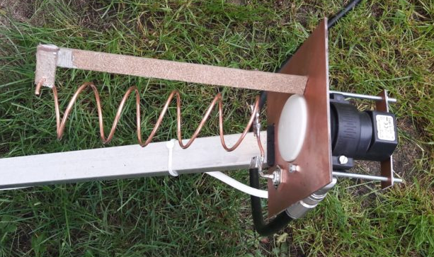
Hélice LHCP avec LNB centré au foyer de la parabole (F5LEN)
a long helix source (left polarization) optimized function of the f/d ratio of the parabola (see Lucien F1TE’s french page). A variant is to associate the LNB centered at the back of the helix (See Pascal F5LEN’s french article). I made my helixantenna with 3/16″ car brake system pipe. The tube is 4.75mm in diameter, with a rigidity that fits perfectly (count 1 meter for a 6 turns helix: ebay link – 10m 3/16″ cuivre)
- a patch antenna
- POTY (patch of the year) : Thanks to its waveguide, this antenna makes it possible to install an LNB at the rear and thus to ensure reception and transmission on the same dish, jointly used with an SDR transmitter/receiver and SDR Console
- DJ7GP (Bamatech), or a DJ7GP associated with a LNB PLL (Bamatech également)
-
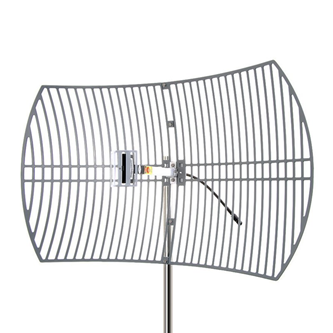

- Even if they are not optimal since they produce a vertical and non-circular polarization wave, they therefore impose a “loss” of 3 dB :
- Wifi grid parabolic antenna (24 dBi) in vertical polarization (Ebay ou Aliexpress)
For DIYers, these antennas can be made by themselves. However, the antenna setting remains impassible for an acceptable return loss of the antenna on 2400 MHz, which is a very effective reason to preserve your amplifiers. To do this, cheap vector analyzers now exist at asian resellers.
Vector Signal Analyzer for your antennas
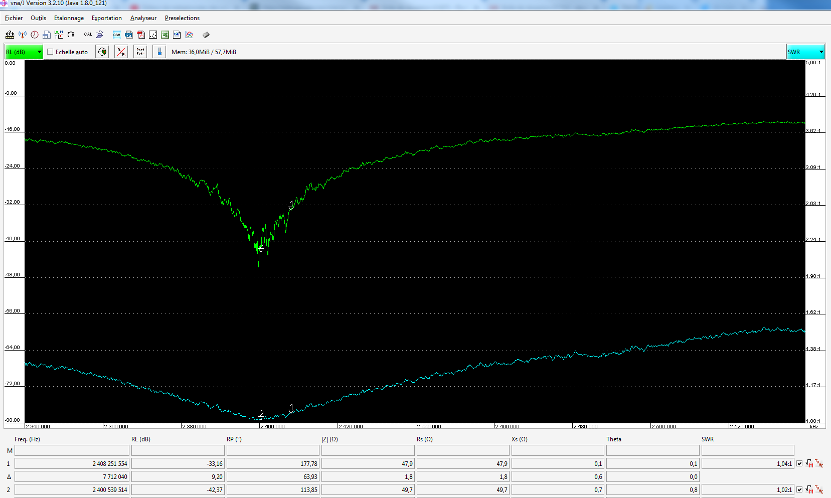
- The miniVNA Tiny de 1 à 3000 MHz and VNA/J software from DL2SBA
- From the Chinese market with these antenna analyzers
- N2201 : 137.5 MHz – 2.7 GHz (link to Aliexpress)
- N1201SA : 140 MHz – 2.7 GHz (link to Aliexpress)
- N1201SA+ : 35 MHz – 2.7GHz (link to Aliexpress)
The amplification
What power for QO-100?
Before even presenting the equipment that will be part of the amplification line, let’s see together what is needed in the terms of power.
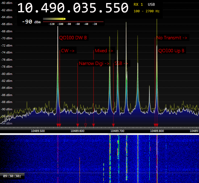
To get trought the satellite, from experience, I use between 0.5 and 5 W with a 1.2m offset dish and DC5GY patch source (powers measured at the focus of the dish itself). In this mode (CW) the signal at 5W is too strong since it is above the level of the beacon (low). We find the power ratio between 0.5W (27 dBm) and 5W (37 dBm) which is worth 10 dBm on the level difference received when the satellite descends (-56 – (-66) = 10 dBm).
If we consider that a signal remains decodable at 10 dBm above the noise level (therefore -80 dBm for my reference of -90 dBm – see capture below), we can emit 14 dBm (80-66) less than the 500mW power used. In other words, with this 1.2m dish and its patch, the CW decodable signal is to be generated with 13 dBm (27-14) or a power of 20 mW ! 

Since the satellite is very sensitive, and the band noise is stable, without variation, a station with 100 mW can be heard and decoded in SSB with this station.
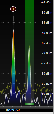
CW signal (tune) at 0.5W with 1.2m dish, to the right of the lower beacon
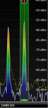
CW signal (tune) at 5W with 1.2m dish, to the right of the lower beacon
Above, here is a recording of a transmission run with 500mW, in SSB.
The following table shows you how the gain on 2400 MHz of parabolas of different sizes evolves. Each time the diameter is doubled, the gain is +6dB, i.e. an equivalent power multiplied by four (This is the case between a parabola of 0.60m and 1.20m, there is 6 dBm). Another reference point. Each time 12.24% is added to the diameter, the gain is +1 dBm (or +25% of power gained).
| Diamètre (mètre) | 2400 MHz | 10400 MHz |
|---|---|---|
| 0.4 | 17.5 | 30.2 |
| 0.6 | 21 | 33.7 |
| 0.8 | 23.4 | 36.2 |
| 0.9 | 24.5 | 37.2 |
| 1 | 25.4 | 38.1 |
| 1.1 | 26.2 | 39 |
| 1.2 | 27 | 39.7 |
| 1.6 | 29.4 | 42.2 |
| 2.4 | 33 | 45.7 |
The amplification line
Now, I propose to focus on the transmission and amplification equipment, individually.
First element, the SDR transmitter
As indicated in the introduction, I only deal here with the case of an SDR transmitter. The power considerations obviously remain the same for a conventional up-converter transmitter.
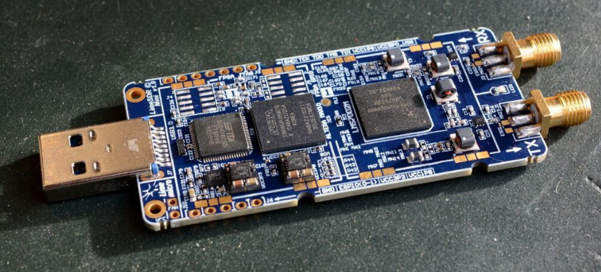
LimeSDR mini
The LimeSDR is an open-source SDR receiver and transmitter USB stick, to be connected to a microcomputer, and covering frequencies from 10MHz to 3.5GHz (for the LimeSDR mini and LimeNET-Micro version) or from 100kHz to 3.8GHz (for the LimeSDR version) and operates in full duplex (simultaneous reception and transmission). Its maximum output power measured at the output of LimeSDR mini is 3 dBm (2mW).

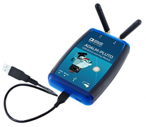
Adalm Pluto Emetteur/Récepteur SDR
Other SDR transmitters / receivers are possible, such as Adalm Pluto from Analog Device (Amazon Link). A modification to improve stabilization is required for narrowband transmission (SSB). I invite you to refer to this modification of the Adalm Pluto of Lucien F1TE’s french article which concerns the replacement of the cristal by a TCXO whose temperature derivation is compensated. Another alternative is to provide a stable 40 MHz reference signal using a GPSDO (GPS disciplinated oscillator) generator
These SDR transmitters can be used for narrowband transmission but also as a broadband transmitter for DATV digital television (Maybe the subject of another article later ?).
Filtering
Before mentioning filters, I would like to recall some points of the regulations concerning the amateur band 2300 – 2450 Mhz. The amateur-satellite service may operate in the bands 435-438 MHz, 1260-1270 MHz, 2400- 2450 MHz, provided that this does not result in harmful interference to other user services. In these bands, the amateur service has a secondary status and any harmful interference caused by satellite emissions must be immediately eliminated (RR provision S5-282). As a reminder, the maximum transmitter output power is 120W (50.8dBm).

It is therefore advisable not to drive the amplifier circuits into their non-linear operating area and to complete the stations, especially SDR, with a 2400 MHz band pass filter after the transmitter.
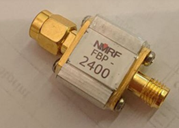
- A cheap filter exists on the Asian reseller market: the 2400 NMRF FBP-2400, with significant losses (4dBm) on 2400 Mhz and its Return Loss -20 dBm (SWR 1.2) Links. Links Aliexpress ou ebay.
- A second one is available in Canada, and sold by GPIO Labs: 2450 GPIO LABS. These losses are less significant (2.4dBm) for the same RL than the previous one. Link to Ebay.
- There are other more professional filters where losses are reduced:ID-Elektronik in Germany
- For do-it-yourselfers, there is a solution that consists in building a resonant cap “Pipe-cap filter”
- KO4BB
- 9A4QV
- W1GHZ (complete documentation Pipe-cap_Filters_Revisited by W1GHZ.pdf)
The preamplification
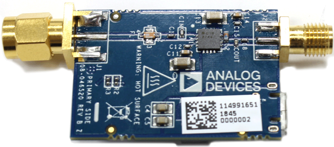
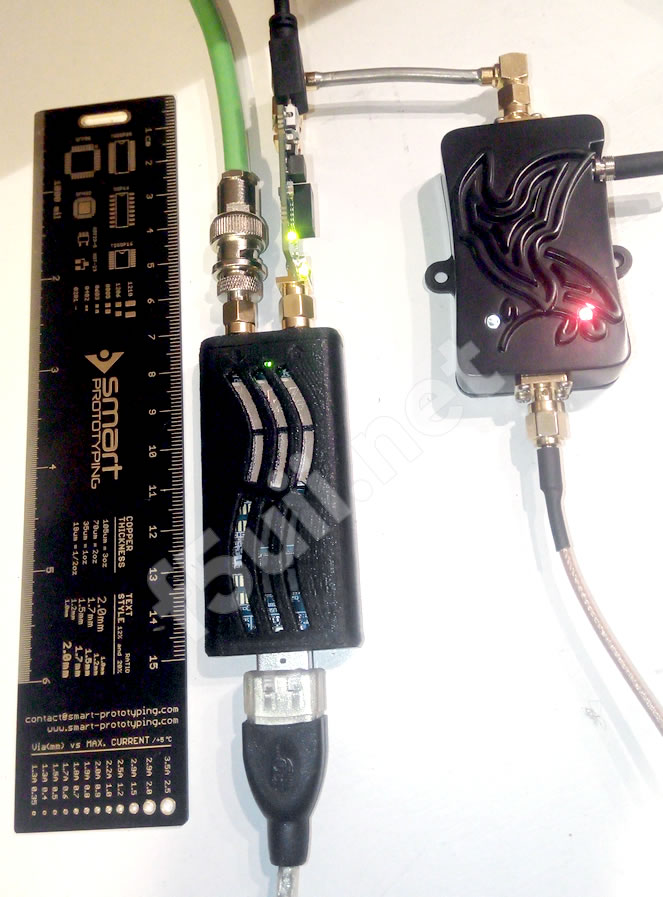
Analog Device CN0417
On the diagram, after the transmitter, you will find a pre-amplification stage for the signal. In this diagram, it is a CN0417 board from Analog Device that is equipped with a two-stage, 1W, two-stage ADL5606 wideband amplifier (see ADL5606 datasheet), which operates over a frequency range from 1800 MHz to 2700 MHz. It integrates an in-line band-pass filter and will provide a 30dBm level output with the LimeSDR mini thanks to its real gain of 20 dB on 2400 MHz. It is powered by a micro-USB plug. Its maximum input level is 18 dBm.
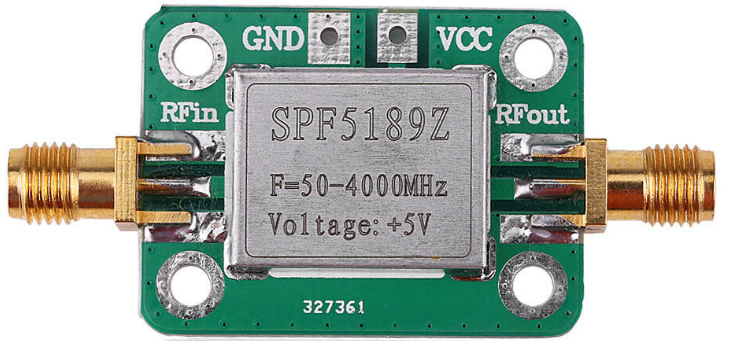
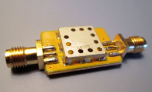
SPF5189Z
Second possibility. The SPF5189Z is a 5V powered preamp that offers 8 to 11 dBm of gain. You will find a detailed measurement report on the Matthias DD1US website. My measurements give me 11 dBm of gain on 2400 MHz. According to the SPF5189z datasheet, the maximum acceptable input is 27 dBm. You can therefore completely cascade two preamplifiers, one after the other. The Chinese reseller market offers them for less than 5 EUR (link SPF5189Z Ebay, link SPF5189Z Aliexpress).

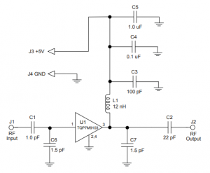
TQP7M9103 pour 2300-2400MHz
Alternatively, there are TQP7M9103 preamplifiers. Depending on the application diagram, you can expect 16 dBm of gain. A QORVO evaluation board exists for 2300-2400 MHz, with an announced gain of 16 dBm. However, this board is very expensive (Mouser USA). There are TQP7M9103 boards of Chinese origin (link Aliexpress 1, Link Aliexpress 2) at low prices, but it is not expected that they will gain on 2400 MHz. You will need to make the changes according to the application diagram for this frequency range. For amateurs, here is the Data Sheet of the Qorvo TQP3M9008 board (see page 16/25) and a link to DK5DN and DL5CN publications on the Amsat-DL forum showing the changes and their results. I have not personally tested the TQP7M9103.
Another alternative is the 2W amplification with the SKY66292-11 transistor. There is a SKY66292-11-EVB evaluation board (Mouser Link USA), which, like the previous amplifier, is offered at a rather high price (Here is the datasheet of the SKY66292_11_EVB board). An alternative is to make this amplifier using the diagrams put online by DB4UM on Github.
A last possibility (that I propose), is based on the Gali-84+ which proposes a gain of 17 dBm on 2400MHz with a maximum input of 0dBm (1mW). It is available on two kits from Minikits (Australia): Gali-84-R2 et Gali-84.
Remember to place an attenuator in front to ensure the maximum permissible input level (Link to attenuators Aliexpress).
The last stage amplification
After the first stage to bring your signal to more or less 200 mW (23 dBm), we can add a last stage of about ten dBm to bring your signal to 2.5 to 3 Watts.
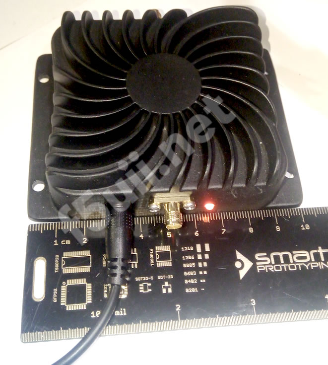
There are two EDUP “booster wifi” amplifiers:
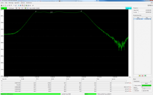
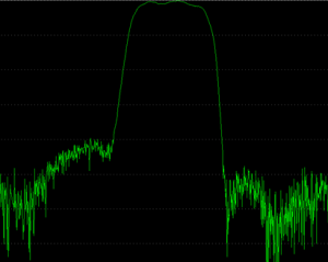
- EDUP AB003, box labelled 8W : The gain of this amp (measured) is 14 dBm. The datasheet indicates a maximum level of 20 dBm signal at the input. Indeed, from 20dBm, the gain itself is reduced but the amplifier can still be used above it. The measurement curve below (red) shows that the gain is reduced to 7 dBm when attacked with 27 dBm at the input, the maximum reached being 35.3 dBm or 3.4 Watts (Link to Aliexpress, Ebay and Amazon)

- EDUP AB007, box labelled 4W : The measurements show an almost identical gain, a little lower at 13 dBm. The maximum signal is 33.8 dBm, or 2.4W. The “4W” amp consumes 10W of electricity and operates nominally at constant RF power between 7.0V and 14V (I didn’t look for the maximum voltage). You can find this equipment on Aliexpress or sur Ebay.
These two amplifiers are duplex wifi amplifiers (transmitter and receiver). We only need the emission amplifier part. The receiver preamplifier, which is active in stand-by mode, is automatically switched on when the input signal exceeds 3dBm when transmitting. Some publications propose to modify the amplifier so that the transmitter remains switched on. This modification is not necessary, as the switching is instantaneous and automatic, and does not bring any significant technical gain.
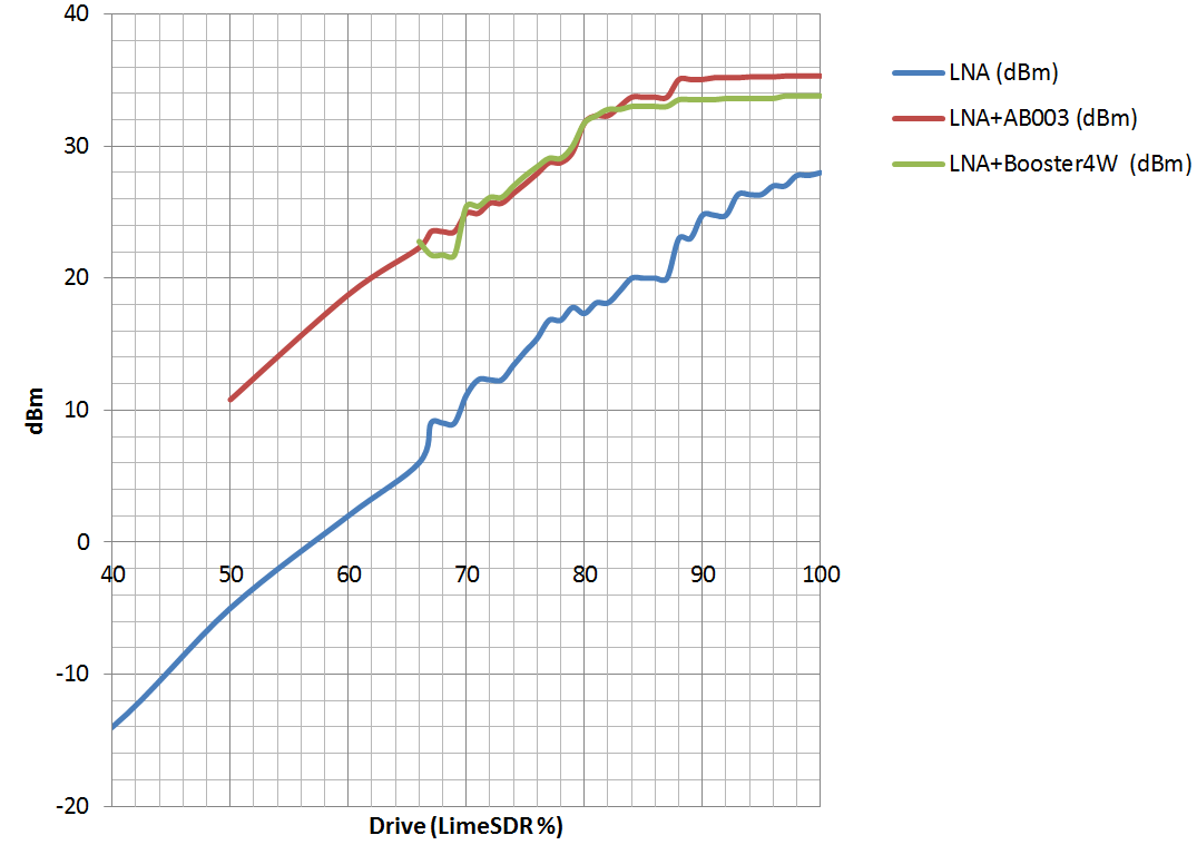
Intermediate power level after CN0417, after EDUP AB003, and EDUP “4W”
For amateurs who would have this need (DATV or small dish), there is also a 20W amplifier not personally tested but measured by DH2VA at a gain of 35dBm up to 15W (Link to Aliexpress).
Measuring devices
The milli-wattmeters
To dispel doubts about power levels, it is useful to equip yourself with a milliwattmeter. It will allow you to check your emissions levels at different points in your emission chain and ensure that you do not apply excessive levels to downstream equipment.
There are also products available on the Chinese market:
-
-
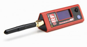
ImmersionRC RF meter
An ImmersionRC wattmeter designed for power measurements of transmitters for models (aircraft, drones) (Link to Aliexpress)
- Power level: -20dBm up to + 30dBm with 30 dBm attenuator included. Runs on rechargeable battery
- Not personally tested
- A “powermeter”, milliwattmeter based on RF detector AD8318 from -55 to -5 dBm (Link to Aliexpress)
- Tested, gives a relative accuracy measurement +/- 1.5 dBm on 2400 MHz
- Use an attenuator (attenuator SMA 30W/30dBm, attenuator N connectors 30W/30dBm) to be connected upstream so as not to exceed the maximum acceptable level (-5dBm)
-


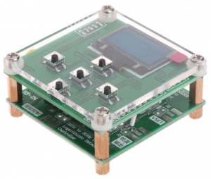
1-8000 Mhz milliwattmeter with -55 to-5 dBm with OLED display and keys
Spectrum analyzer
A spectrum analyzer can also be used to measure levels and check the spectral “purity” of your transmitters. Always be careful that you do not apply a higher level that is acceptable to your analyzer. An analyser with tracking (generator), combined with a directional coupler, will also allow you to determine the return loss of an antenna. For amateurs, I suggest you watch this video explaining the measurement method. Resources (in french) are also available on the REF 68 website.

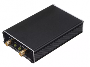
LTDZ 35-4400M spectrum analyzer
I suggest you to discover this ultra portable spectrum analyzer LTDZ 35-4400M connectable to a Windows
SDR Console settings
Step by step

- Follow the instructions for installing the driver for your equipment
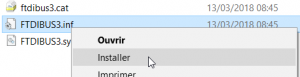
- In the case of LimeSDR, install the LimeSDR USB driver [ download, FTD3XXDriver_WHQLCertified_v1.3.0.0.2.zip or newer, unzip, and in the directory corresponding to your installation_ 32 or 64 bits, OS version then install the FTDI driver – inf file ]
- In the case of LimeSDR, install the LimeSDR USB driver [ download, FTD3XXDriver_WHQLCertified_v1.3.0.0.2.zip or newer, unzip, and in the directory corresponding to your installation_ 32 or 64 bits, OS version then install the FTDI driver – inf file ]
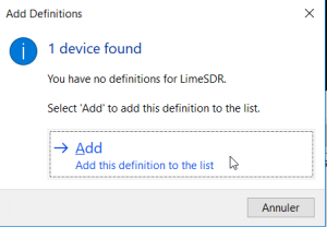
- Run SDR Console. At the first launch, the software suggests that you search for your SDR equipment, which must be connected to your computer.
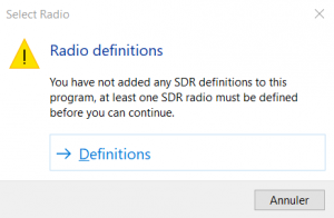
- On the Radio Definitions window, click Search to add your equipment that you have connected to the computer. Here I am looking for the LimeSDR key.
- The key is then added to my “Radios” configuration. Don’t forget to click on the “Save” button.
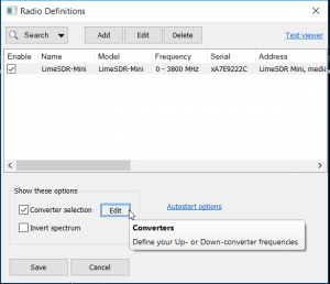
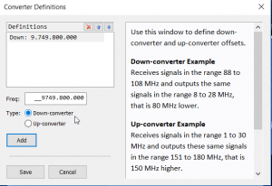
- I now invite you to follow the SDR Console setup steps already published in my previous article on reception (from Conversion Frequencies subsection, to the bottom of the page, so that reception is implemented, and the frequency stabilized automatically.
- Start SDR Console
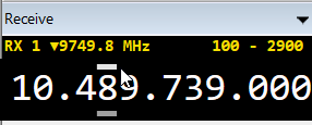
- Set the reception frequency by typing or clicking on the sliders above and below each digit of the reception panel
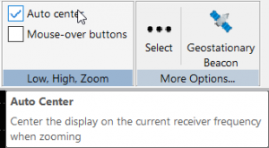
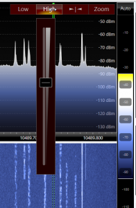
- Adjust the signal levels displayed on the spectrum, using the Low, High and Zoom sliders, buttons that appear at the top right of the spectrum. For my part, once the Low and High levels have been set, only the zoom is useful (On the View tab, Low, High, Zoom subpart, I uncheck Mouse-over buttons, and tick Auto center so that the zoom is always done around the reception channel.
- Here are some settings I make to improve the quality of reception :
- On the left panel Receive, click AGC = Off, and push the reception gain. This reduces some noise.
- Activate the NR1 noise reducer and adjust around 8 dB.
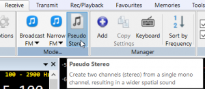
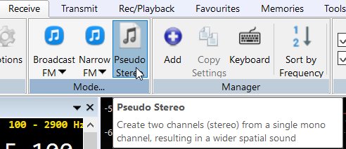
- Enable the pseudo stereo function that enhances listening (check Enable and keep the default settings)
- On the left panel Receive, click AGC = Off, and push the reception gain. This reduces some noise.
- Now that we have active reception and frequency adjustment (thanks to the stabilization feature), we will proceed to transmission: display the transmission control panel via the Transmit menu, then the DSP button. The Transmit side panel is present on the right side of the screen. This panel can only be displayed for SDR equipment with the transmit function. For LimeSDR, only the 750 kHz bandwidth offers this possibility.
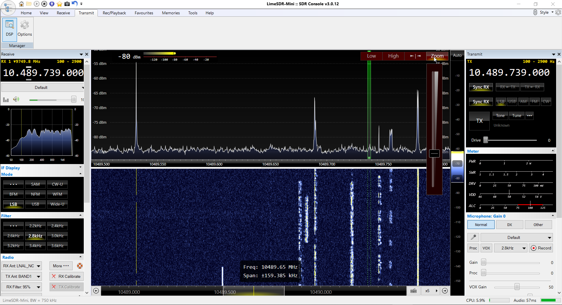
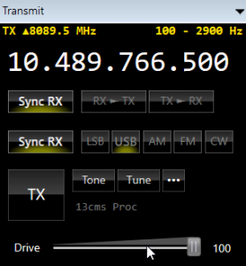
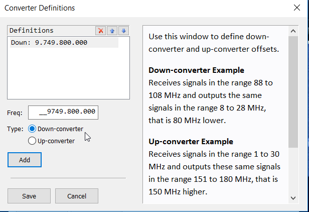
- Now set the shift on transmission (frequency difference between the displayed reception signal and the transmission frequency): This difference is constant and is equal to 8089.5 MHz. (10489.800 – 2400.300). This will allow you to transmit on the correct up frequency to the satellite with a simple click on the signal of a received station and be able to respond to that station.
- Set the USB reception mode and click on the transmitted panel on the bottom Sync RX button (this copies the reception mode). By activating the upper Sync RX button, you will always have the same transmit frequency as the selected receive frequency. In use, I prefer not to activate this synchronization and instead use the RX > TX button which copies the transmission frequency on demand. This allows you to follow a signal from a station whose frequency drifts without changing the transmission frequency to the satellite.
Connect a microphone to your PC, or use the internal microphone of your laptop. The solution of a headset is recommended in order to benefit from the reception quality (pseudo-stereo) and avoid that you send back by through the satellite again the sound incoming the microphone. This effect generates echo and feedback.
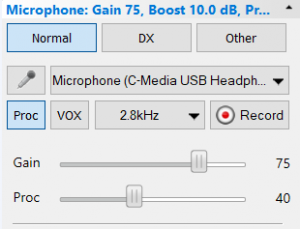
Select the corresponding microphone audio channel on the Transmit panel. Increase the gain by pushing the slider to the right.
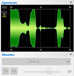
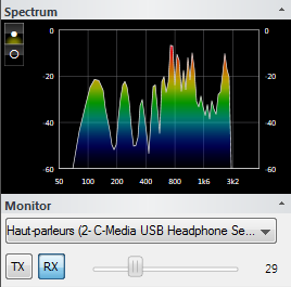
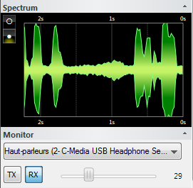
- Before you even pass in transmission, check at the bottom of the Transmit panel that the audio signal appears in the Spectrum oscilloscope when you speak.

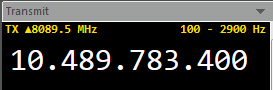
- Set your transmission frequency in the satellite band. If you have properly set up the shift as described above, it is normal that the frequency displayed below 10 GHz.
- Before switching to SSB transmit, I invite you to check your transmission using the Tune button, which emits a tone. Adjust the power level of your signal with the horizontal Drive slider. You should see your satellite signal when you receive it. Stop the transmission by clicking on the same button.
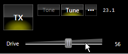
- To switch to SSB transmission now, click on the square TX button. While the TX button is active, you will need to increase the power level of your SDR transmitter by sliding the Drive slider to the right. With full-duplex reception you should get along with the satellite in feedback.


Tips
- You can listen to the audio transmitted locally thanks to the Monitoring available at the bottom of the Transmit panel. Click on RX to hear the audio as it will be transmitted by your SDR transmitter. The oscilloscope or FFT analyzer allows you to control your transmission.
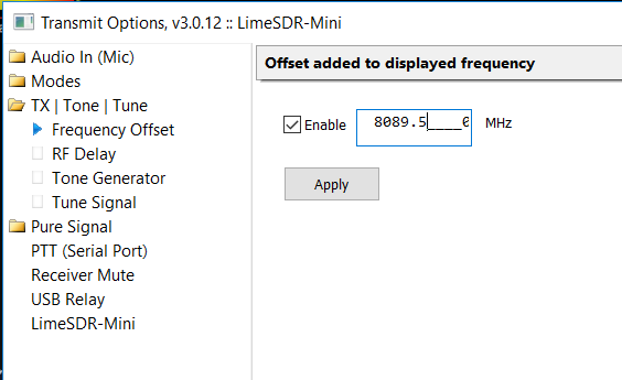
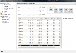
- If you find that the audio level is not sufficient despite the microphone’s high gain, you can add a constant gain of a few dB. In the SDR Console’s Transmit top menu, click on Options. In Audio In (Mic) choose Gains to choose a microphone boost level. Note that on this panel, you also find a way to limit the audio and RF levels by frequency band. This may be interesting if you plan to use your SDR equipment for transmission on other bands.
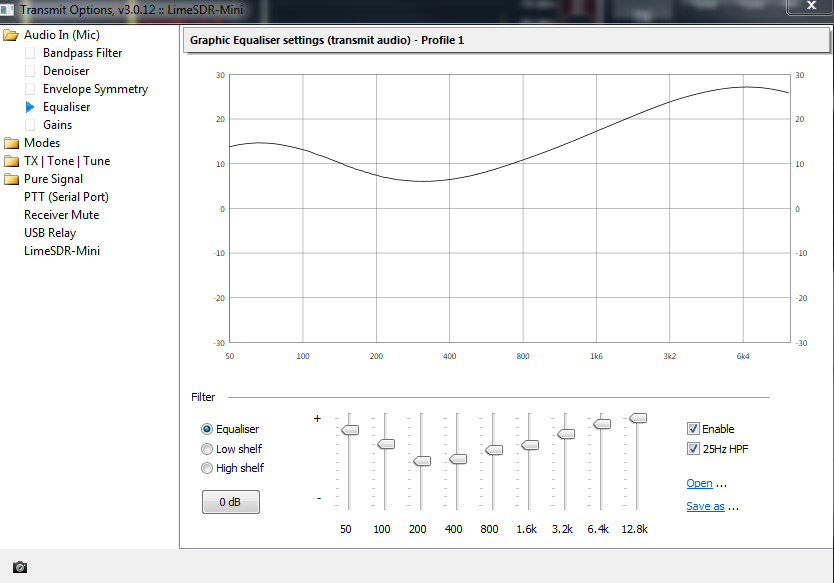
- Like the equalizer that exists for reception, you can “correct” the audio transmitted by your microphone using the dedicated equalizer for transmission. In the top menu Transmit, click on Options. In Audio In (Mic) choose Equalize to adjust as desired. You do not have to close this panel to hear the result of your adjustments.
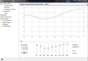
Equaliseur audio de la voie d’émission
- In the environment of amateur radio stations, there is often background noise from forced ventilation. SDR Console includes a digital filter that significantly reduces these types of sounds.
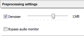
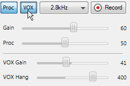
- The audio processor can be switched on with the [Proc] button and its level adjusted from the Transmit panel
- When you switch to transmission, you can reduce the audio level of the reception. This will allow you to stay tuned while not disturbing the audio level (this is required by the satellite usage rules published by AMSAT-DL). In the top menu Transmit of SDR Console, click on Options. In Receiver Mute, check Enable and adjust the level of the reception signal as desired.
- Your SDR transmitter may not be exactly set to the frequency corresponding to the reception. To correct this, you will activate the offset function on XIT transmission. In the Receive panel of SDR Console, activate the XIT button and adjust the correction frequency until you hear your signal from the satellite in the same tone as what you generate locally.
-
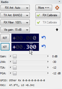
Activer le décalage XIT pour corriger votre fréquence à l’émission


A voice keyer with SDR Console
The Transmit panel of SDR Console offers 3 buttons that allow you to switch different audio sources and their settings. The buttons are labeled Normal, DX and Other.
For each button, you can define independent settings, including specific sound cards. I propose to you step by step the implementation of a voice keyer.
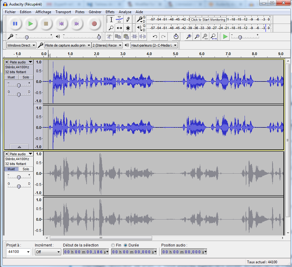
- Install recording software such as Audacity. This software is free and has many audio signal processing functions (filter, editing, noise reduction…). You can also simply use the Windows standard recorder.
- Record your CQ call with your most beautiful voice. Save the project.
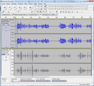
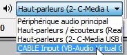
- To be able to properly “inject” your recording to SDR Console, we will install two virtual audio channels. Download and install VB-CABLE Virtual Audio Device.
- On Windows, two new audio channels are now available: a Cable Input channel and a Cable Output channel. The two channels are connected together. As soon as a sound is sent on Cable Input, it is available on Cable Output. To be able to use the new audio channels, restart SDR Console and Audacity.
- On the Transmit panel, we will consider that with the Normal button, you will configure your microphone with which you usually work.
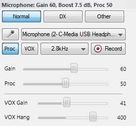
Voie Normal pour le microphone habituel
- Now, let’s configure the DX button, which will have to be switched to activate it for your caller. Choose CABLE Output, and switch on the VOX.
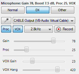
Voie pour la source externe
- Now, on your audio player, switch the audio output to CABLE Input.
Start playback of your recording in your audio player. This is sent via the Cable Input/Cable Output channel to SDR Console, which immediately switches to transmission using the VOX function. On Audacity, to start playing your recording in a loop, hold down the Shift key on the keyboard before clicking on Play (or directly at the keyboard shortcut: Shift + space bar). If you have an answer to your call via satellite, you will click on the Normal button on the Transmit panel of SDR Console, so that your usual microphone is operational again.


The band limits
Since version 3.0.11 of SDR Console, it is possible to integrate markers on the spectrum. On my configuration, I added the band plan limits for traffic on the QO100 satellite.

I invite you to do the same, by downloading my already configured file.
- Download my file SDRConsole BandMap QO100 F5UII.CSV
- On the View tab (menu), click on Markers.
- On the Spectrum Makers window, click on the”…” button and choose CSV Import. Point on the downloaded file.
- Select all lines and then OK. Close the “Spectrum Makers” window
So here is my second article about the satellite traffic on Qatar Oscar 100 (Es’Hail 2) and the SDR Console software. This software developed by Simon G4ELI is really very pleasant to use, in reception and transmission. It is pleasant to be able to answer a calling station, by a simple click on the waterfall, and transmit precisely on its frequency. I would like to thank Simon G4ELI for the development of this software of very high quality, stability and functionality.
Your SDR transmitter (LimeSDR, Adalm Pluto) can be used for a DATV transmission station. Maybe this could be the subject of another article in my blog, who knows….
Feel free to share your experiences, remarks by using directly the comments below. I would like to inform you that for your technical support needs, this is done only through public comments directly on this page, so that all readers can contribute. No support by private contact will be provided. I also invite you to follow my twitter account @f5uii dedicated exclusively to amateur radio activities, and on which many news and technical information are exchanged.
Very good listening and very good traffic on the Es’hail 2 satellite / Phase 4A / Qatar Oscar 100 !