To realize a multimode digital repeater, G4KLX has developed a very complete software called MMDVM (Multimode Digital Voice Modem). It is compatible with the main digital modes (to date, C4FM, DSTAR, DMR Tier 2 and now P25).
 After my previous MMDVM interface card with an Arduino Due, this new shield realize the interface between transmitter and receiver with the STM32F446RE ST Microelectronics Nucleo board. This board has the advantage of speed up at a rate of 8 MHz (CPU frequency up to 180 MHz), and has a rather low purchase price (about 15 EUR excl. VAT). A computer (such as a Raspberry Pi for example) connect via USB to the STM32 completes the relaêater controler and hosts the second part of the MMDVMHost software.
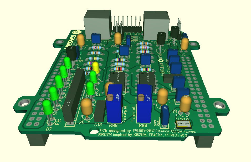
I realized this PCB trace, like some other OM, with components of classic sizes (integrated circuits in DIL format, resistances in quarter of Watt, …). There is only the TCXO which remains rather small. To get rid of a SMD formatting component, I chose to install a TCXO HCMOS directly compatible with 3.3V. The reference chosen is FOX924B-12 with a stated stability of +/- 2.5 ppm.
The plate is inserted directly below the Nucleo STM32 board, on CN7 and CN10 connectors.
The following features have been added to the previous MMDVM interface card running with an Arduino Due:
- Measurement of RSSI signals sent by the receiver (with validation jumper)
- An LED signaling the life of the deck (Live Led)
- Four LEDs indicating the active mode (DStar, DMR, YSF, P25)
- Integrated radio interface pins between the two mini-Din connectors
- Switching to a single mini-Din connector Transmitter / Receiver
- Nextion touch screen LCD interface
- Four additional mounting brackets 3mm (50.00mm x 75.56mm)
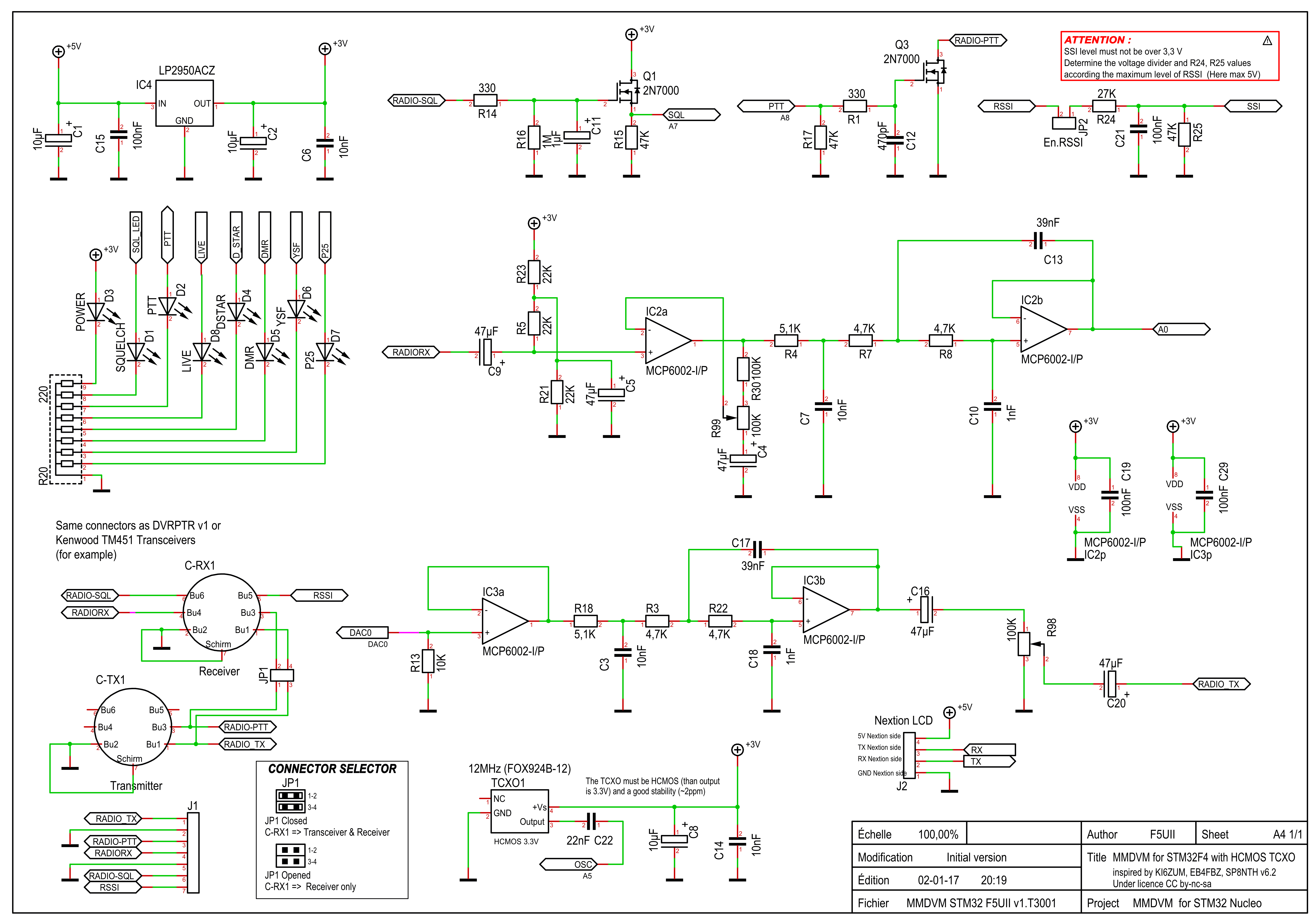
Diagram of the MMDVM board for Nucleo STM32F4 – The MMDVM filter is under CC BY / SA / NC license established by KI6ZUM
PDF Format : Diagram MMDVM shield for STM32
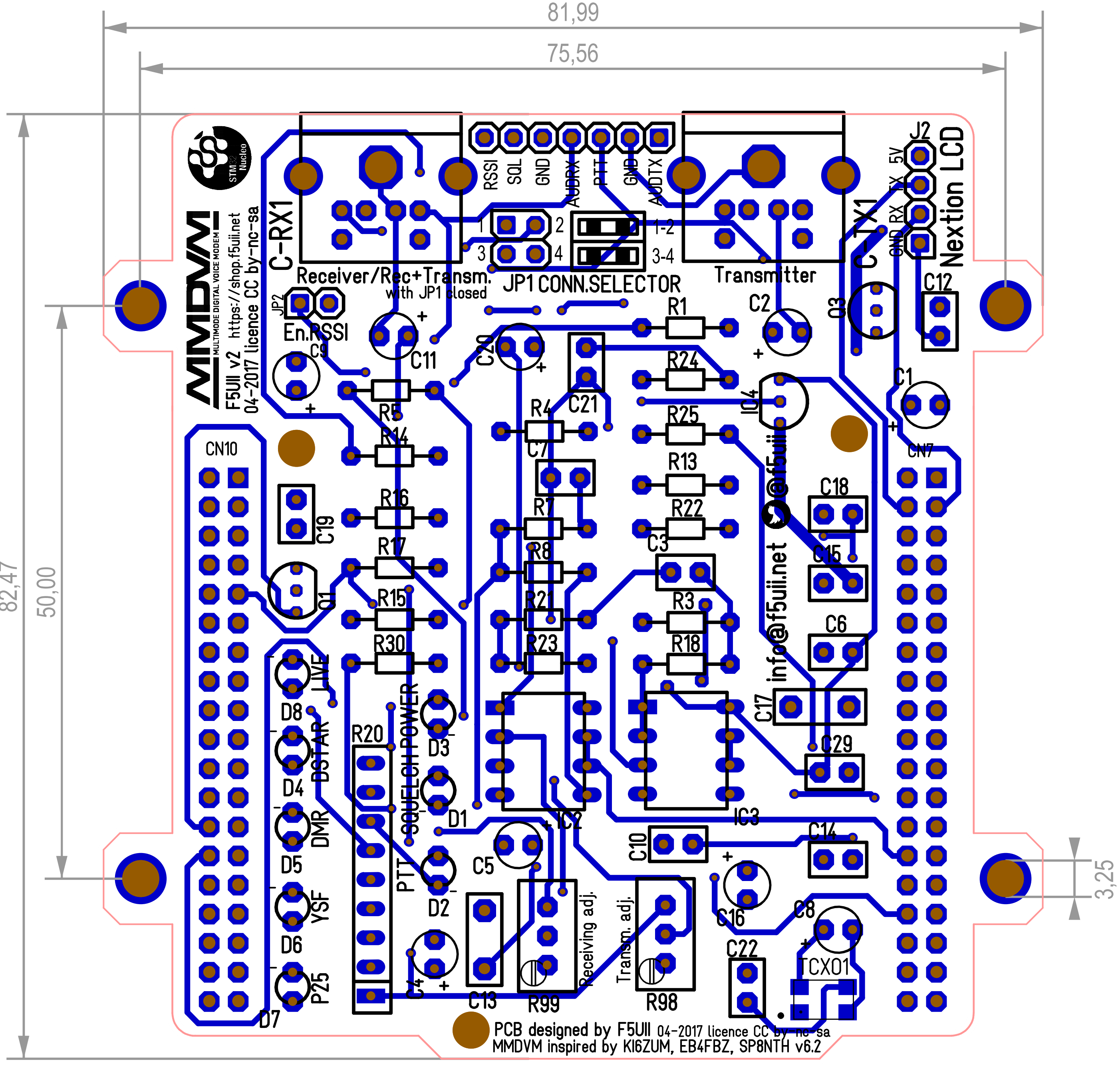
MMDVM shield for Nucleo STM32 (Top view – dimensions in mm)
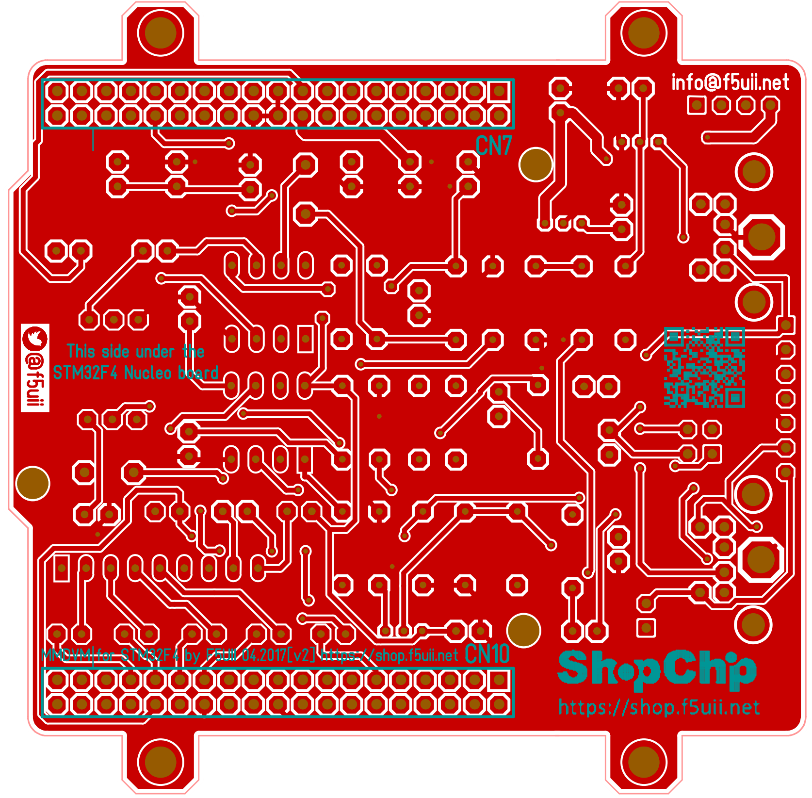
MMDVM shield for STM32 – Rear face with ground plane, with 2 femal connectors
Here the Bill Of Materials:
| Name | Value | Precision | Mounting box |
| C1 | 10µF | D4R2,54_ELKO | |
| C2 | 10µF | D4R2,54_ELKO | |
| C3 | 10nF | 10% | 3X5R2,54 |
| C4 | 47µF | D4R2,54_ELKO | |
| C5 | 47µF | D4R2,54_ELKO | |
| C6 | 10nF | 10% | 3X5R2,54 |
| C7 | 10nF | 10% | 3X5R2,54 |
| C8 | 10µF | D4R2,54_ELKO | |
| C9 | 47µF | D4R2,54_ELKO | |
| C10 | 1nF | 5% | 3X5R2,54 |
| C11 | 1µF | D4R2,54_ELKO | |
| C12 | 470pF | 3X5R2,54 | |
| C13 | 39nF | 5% | 3X8R5,08 |
| C14 | 10nF | 10% | 3X5R2,54 |
| C15 | 100nF | 3X5R2,54 | |
| C16 | 47µF | D4R2,54_ELKO | |
| C17 | 39nF | 5% | 3X8R5,08 |
| C18 | 1nF | 5% | 3X5R2,54 |
| C19 | 100nF | 3X5R2,54 | |
| C20 | 47µF | D4R2,54_ELKO | |
| C21 | 100nF | 3X5R2,54 | |
| C22 | 22nF | 3X5R2,54 | |
| C29 | 100nF | 3X5R2,54 | |
| C-RX1 | Receiver | DIN6POL-MINI | |
| C-TX1 | Transmitter | DIN6POL-MINI | |
| D1 | LED SQUELCH | LED_3mm_vert | |
| D2 | LED PTT | LED_3mm_rouge | |
| D3 | LED POWER | LED_3mm_jaune | |
| D4 | LED DSTAR | LED_3mm_vert | |
| D5 | LED DMR | LED_3mm_vert | |
| D6 | LED YSF | LED_3mm_vert | |
| D7 | LED P25 | LED_3mm_vert | |
| D8 | LED LIVE | LED_3mm_jaune | |
| IC2 | MCP6002-I/P | DIL8 | |
| IC3 | MCP6002-I/P | DIL8 | |
| IC4 | LP2950ACZ3,3 | TO92 | |
| Q1 | 2N7000 | TO92 | |
| Q3 | 2N7000 | TO92 | |
| R1 | 330 | 0204_MET | |
| R3 | 4,7K | 1% | 0204_MET |
| R4 | 5,1K | 1% | 0204_MET |
| R5 | 22K | 1% | 0204_MET |
| R7 | 4,7K | 1% | 0204_MET |
| R8 | 4,7K | 1% | 0204_MET |
| R13 | 10K | 0204_MET | |
| R14 | 330 | 0204_MET | |
| R15 | 47K | 0204_MET | |
| R16 | 1M | 0204_MET | |
| R17 | 47K | 0204_MET | |
| R18 | 5,1K | 1% | 0204_MET |
| R20 | 220 x 8 | SIL9 | |
| R21 | 22K | 1% | 0204_MET |
| R22 | 4,7K | 1% | 0204_MET |
| R23 | 22K | 1% | 0204_MET |
| R24 | 27K | 0204_MET | |
| R25 | 47K | 0204_MET | |
| R30 | 100K | 0204_MET | |
| R98 | 100K | VISHAY_64W | |
| R99 | 100K | VISHAY_64W | |
| TCXO1 | 12MHz (FOX924B-12) | CFPX-104 | |
| J1 | Radio interfaces | Stiftleiste_1x07_G_2,54 | |
| J2 | Nextion LCD | Stiftleiste_1x04_G_2,54 | |
| JP1 | Connector Sel. | Stiftleiste_2x02_G_2,54 | |
| JP2 | En.RSSI | Stiftleiste_1x02_G_2,54 | |
| CN7, CN20 | Female conn. 2×19 | Stiftleiste_2x19_F_2,54 | |
In order to make your copy of the electronic card, you will find here all the production and drilling files of the standard Gerber card : MMDVM STM32 F5UII v2 – licenced CC by-nc-sa
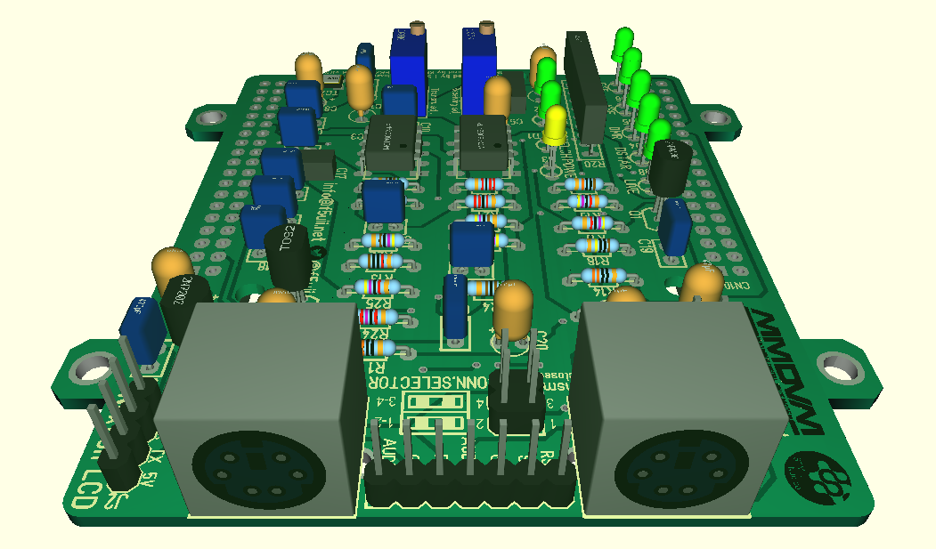
Here is the board mounted, tested and functional
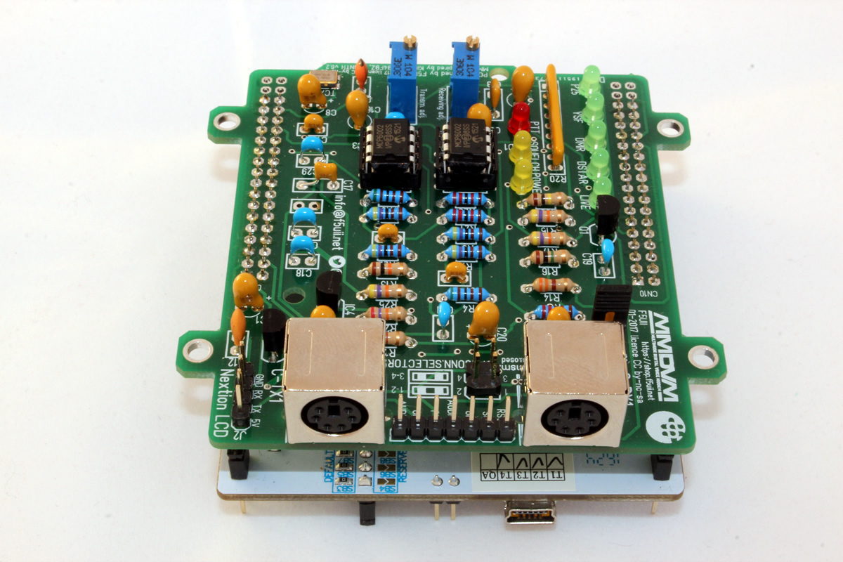
MMDVM shield mounted under the STM32 board of ST Microelectronics
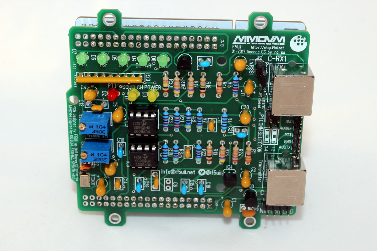
The STM32F4446RE behind the MMDVM filtering shield
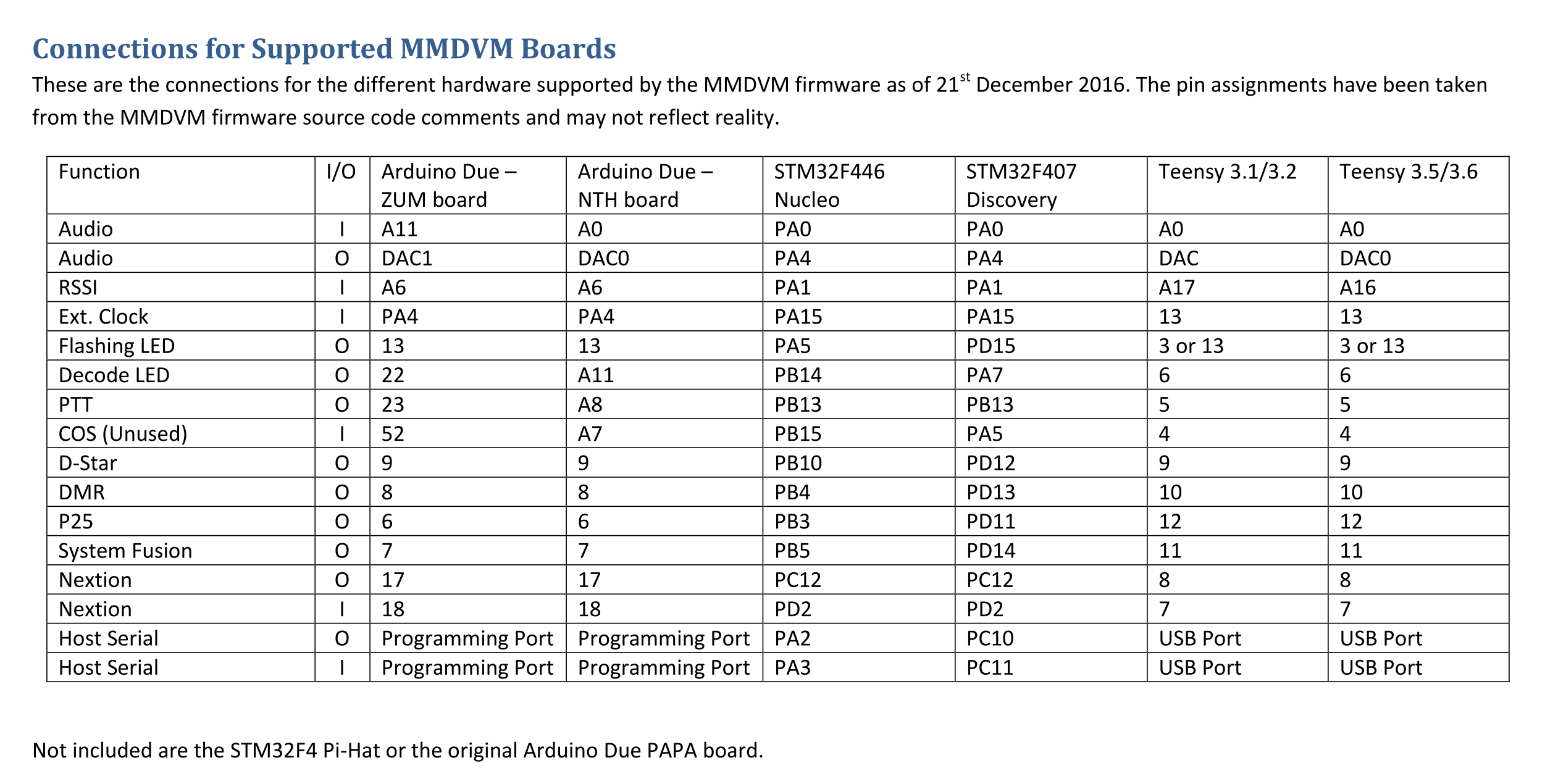
In the table below, you will find the pinout to follow according to the board. Like my previous MMDVM board for Arduino uses the NTH definition.
Sur le tableau ci-dessous, vous retrouvez le brochage à suivre en fonction de la platine. Comme ma précédente platine MMDVM pour Arduino utilise la définition NTH.
 Once your shield is mounted, you will probably be in a hurry to load the MMDVM firmware and set MMDVM on the STM32 interface board: MMDVM installation on a STM32F4xx board
And for tuning, I invite you to read the article dedicated to the installation of MMDVHost and the DMR mode calibration.
If you are interested to participate in a possible future new grouped order, leave your email below to be reported !
Hi ,
Made the board using the Geber files .
Seem to have a problem a soon i connect the TCXO .. i can’t program the board anymore .
STM-32 link gives errors .. as soon i remove C22 .. it works fine to program .
checked the TCXO with scope .. perfect 12Mhz ..
73
Tom
Hello Tom,
I do not understanding how it can be a link with the STM-32 programming failing, and the C22.
I have mounted 22nF for C22, but 22pF is the normal value. If you can, have a try with 22pF.
Actually, have you suppress C22 and put a strap for continuity of the signal ?
Regards,
Yes i tryed with a bridge on C22 ..
Same problem .. it’s really weird , on the SP8NTH it’s indeed 22pf .
Dit not try that yet .
Werid this is . have it on 2 boards i made .
A soon a remove C22 or the bridge .. i can program w/o problems .
Dear Sir , Can you advise on shield for Discovery STM32F4 boards, if possible please? Or an adaptor board for SP8NTH for this one ?
Adrian,
I This MMDVM shield is yes inspired from SP8NTH schematic and will be plugged under a Nucleo STM32F446RE, but not for the Discovery version board. I do not know if this shield is existing somewhere. Sorry.
regards
Hello
Thanks your effort. And I would like to ask a question. What is the output voltage of LP2950ACZ ? does is 3V or 3V3 ?
As I found the Txco work on 3V3, but your circuit diagram marked the 3V only for the output of LP2950ACZ.
(Traduction)
Bonjour
Merci de votre travail. Et j’aimerais poser une question. Quelle est la tension de sortie de LP2950ACZ? Est-ce que c’est 3V ou 3V3?
Comme j’ai trouvé le travail de Txco sur 3V3, mais votre diagramme de circuit a marqué le 3V uniquement pour la sortie de LP2950ACZ.
Thank you Francis,
The supply must be 3,3V. I installed a LP2950ACZ-3,3 , that is thecomplete reference. I will precise it above.
Thank for remarks.
(Traduction)
Merci Francis,
L’alimentation doit être de 3,3V. J’ai installé un LP2950ACZ-3,3, voilà la référence complète. Je vais le préciser ci-dessus.
Merci pour les remarques.
IMPORTANTE INFORMATION :
The STM32 gerber v1 included a big mistake ! The output of TCXO coming from C22 is wiring to pin 15 of CN7. It should have been connected to pin 17 CN7 !
For those who would have realized the board based on the Gerber v1 file, you can correct this problem by opening C22 upper pin and connect it with a little wire to pin 17 of CN7 (9th row, right side of the board).
Sorry for inconvenience.
The Gerber v2 is correct now.
—-
INFORMATION IMPORTANTE:
Le STM32 gerber v1 a inclus une grosse erreur! La sortie de TCXO provenant de C22 est le câblage de la broche 15 du CN7. Il aurait dû être connecté à la broche 17 CN7!
Pour ceux qui auraient réalisé la platine sur la base du fichier Gerber v1, vous pouvez corriger ce problème en ouvrant la broche supérieure de C22 et la connecter avec un petit fil à la pin 17 du CN7 (9ème rangée, côté droit de la carte).
Désolé pour les inconvénients.
Le Gerber v2 est correct maintenant.
Thanks for the fix and al your efforts Christian !
here is a picture of the mod .
(Traduction)
Merci pour la correction et tous vos efforts, Christian!
Voici une image de la modif.
Thank you Tom for you testing. The gerber (v2) is updated as the top/bottom board images.
Merci Tom pour les tests. Le gerber (v2) est à jour ainsi que les images de la platine.
So besides the C22 pin 15 of CN7 problem. Does the C22 also unnecessary, which can be removed (short the pins together).
(Traduction)
Donc, outre le soucis du raccordement de C22 à la pin 15 du CN7, le C22 est-il également inutile, et être supprimé (ou broches mises ensemble).
Hi Francis,
As you want, you can remove C22 like Tom has done (see above on picture) or let C22 online. So cut the upper pin (The one positioned nearby C16) and solder a wire on this up pin to CN7/17
Comme vous le souhaitez, vous pouvez supprimer comme Tom l’a fait (voir ci-dessus sur la photo) ou laisser C22 en ligne. Coupez alors la pate du haut (celle positionné prêt de C16) et soudez un fil sur cette patte en l’air vers le CN7 / 17
Someone tried to short CN7/15 and CN7/17 ?
If pin15 is in high impedence ( eg. output mode ) is too easy to fix !
73
(traduction)
Quelqu’un a-t-il essayé de court circuiter CN7/15 et CN7/17 ?
Si pin 15 est en haute impédance (en mode de sortie), cela serait trop facile à règler !
73
made another V1 board with the nicer fix .
(Traduction)
Voici une platine V1 avec correction plus sympa
I’m having problems with DMR reception into the repeater (DR1-X). Made the mod to connect TCXO pin 17 with/without 22 nF cap, but the modem will not decode DMR. Played with levels and looked ADC input with scope. All look comparible to my working Arduino Due based modem. Also tried an attenuator on the Disc output because I was seeing ADC overflow messages on DStar. No luck at all with DMR. No messages in MMDVMHost console when I TX with several different DMR HT’s.
Receives and transmits DStar fine and transmits DMR network traffic OK. Adjusted TX deviation with Bessel null method which worked normally. The 446RE is running the latest FW and the host is also the current release. It compiled and installed without issue and is set up for a 12 MHz TCXO. The oscillator signal looks fine on the scope and is running at 12 MHz.
Any troubleshooting tips and hints with MMDVM.ini settings appreciated. I am using RX and TX invert=1 and that seems to work with DStar, but tried various settings. Anyway to verify the STM32 is running on the external clock?
Thanks
Dave, K7DMK
Well, I found the problem. It was a bad op-amp in the receive chain on the F5UII board. The bottom half of a sine wave test signal was being cut off when fed into the RX input. When I measured the bias voltage on the virtual ground voltage divider it was only about 1.1V instead of 3.3/2 or 1.65V. The bad op-amp input was pulling down the voltage instead of presenting a very high input impedance.
Luckily I had installed IC sockets for the amps so it was a quick fix to replace the bad part.
DMR decode is now working. Interestingly, DStar decode did not seem to be affected.
Dave, K7DMK
(Traduction)
Voila, j’ai trouvé la source du problème. C’était un mauvais ampli-op installé dans la chaîne de réception sur la carte F5UII. La moitié inférieure du signal de test sinusoïdal était coupée lorsque placé dans l’entrée RX. Quand je mesure la tension de polarisation sur le diviseur virtuel de tension de masse, il n’y avait que seulement 1.1V au lieu de 3,3 / 2 ou 1.65V. La mauvaise entrée ampli-op tirant alors vers le bas la tension au lieu de présenter une impédance d’entrée très élevée.
Heureusement, j’avais installé des supports de circuits intégrés pour les amplis de sorte qu’il était rapide de remplacer la pièce défectueuse.
Le décodage DMR fonctionne maintenant. Fait intéressant, DStar ne semblait pas être affecté par le problème.
Dave, K7DMK
Question about DMR & Hytera radios.
Dave, please email me.
Tim
N8NQH
Some body know Why I has this error https://youtu.be/99kFPkjuyf0 Thanks
Mauro
PS. mmdvm V6.2 NUCLEO -F446re
(Traduction)
Certains savent pourquoi j’ai cette erreur https://youtu.be/99kFPkjuyf0 Merci.
Mauro
PS. mmdvm V6.2 NUCLEO -F446re
Yes, Mauro,
The STM32F4XX_Lib directory must be put in the MMDVM directory before compiling.
see https://github.com/g4klx/MMDVM/issues/116
otherwise, you have this error.
RSSIRB.cpp: In constructor 'CRSSIRB::CRSSIRB(uint16_t)':RSSIRB.cpp:25:8: error: 'NULL' was not declared in this scope
m_rssi(NULL),
(Traduction)
Oui Mauro,
Il faut mettre le répertoire STM32F4XX_Lib dans le répertoire MMDVM avant de compiler.
voir https://github.com/g4klx/MMDVM/issues/116
sinon en effet, vous avez cette erreur
RSSIRB.cpp: In constructor 'CRSSIRB::CRSSIRB(uint16_t)':RSSIRB.cpp:25:8: error: 'NULL' was not declared in this scope
m_rssi(NULL),
After recording the firmware it was time to record the pi-star on the raspberry pi-star and test the MMDVM stm32nucleo and the result was that it does not encode the digital signals even trying to adjust on the resistor R98 some help .
https://youtu.be/GNTEBuOfwUQ
Thanks
(Traduction)
Après chargement du firmware, il était temps de démarrer le pi-star sur la Raspberry Pi et de tester le MMDVM sur stm32nucleo. Résultat, cela n’encode pas les signaux numériques même en essayant d’ajuster sur la résistance R98. Quelqu’un peut-il m’aider ?
https://youtu.be/GNTEBuOfwUQ
Merci
Hi, my problem is opposite from you, my board can receive and decode, but one it transmit. No sound at all, even the cw id does not come out. It does PTT. I tried turning the 2 potentiometer, increase audio on mmdvmcal. But no luck.
Need help, thank you very much
(Traduction)
Bonjour, mon problème est inverse à vous, ma carte peut recevoir et décoder, mais elle transmet pas. Pas de son du tout, même l’ID CW ne sort pas. Elle passe en PTT. J’ai essayé de tourner les 2 potentiomètres, et augmenter l’audio sur mmdvmcal. Mais pas de résultat.
Besoin d’aide, merci beaucoup.
Hello Mauro, Hello Dennis,
Have you verify that the right TCXO frequency writen in MMDVM
Config.h[#define EXTERNAL_OSC 12000000]?Have a look also to this comment
Check the log file of MMDVM in realtime with this command:
tail -f $(find /*.log -type f -printf '%T@ %p\n' | sort -n | tail -1 | cut -f2- -d" ")(Traduction)
Bonjour Mauro, bonjour Dennis,
Avez-vous vérifié que la bonne fréquence TCXO (12,000 or 12,288 MHz) est écrite dans MMDVM
Config.h[#define EXTERNAL_OSC 12000000]?Jetez également un coup d’oeil à ce commentaire “.
Vérifiez le fichier journal de MMDVM en temps réel avec cette commande:
tail -f $(find /*.log -type f -printf '%T@ %p\n' | sort -n | tail -1 | cut -f2- -d" ")Mauro,
On your video, all steps seem ok. I’m not a Pi Star user, but on your video, I saw that on the Pi-Star configuration page, you do not have validated the DMR Mode in MMDVMHost Configuration part. Do you have to switch the button left to enabling DMR Mode ?
73 Chris
(Traduction)
Mauro,
Sur votre vidéo, toutes les étapes semblent correctes. Je ne suis pas un utilisateur de Pi Star, mais sur votre vidéo, j’ai vu que sur la page de configuration Pi-Star, vous n’avez pas validé le mode DMR dans la partie MMDVMHost Configuration. Ne faut-il activer le mode DMR en positionnant le bouton à gauche ?
73 Christian
// For 12 MHz// #define EXTERNAL_OSC 12000000
// For 12.288 MHz
#define EXTERNAL_OSC 12288000
// For 14.4 MHz
// #define EXTERNAL_OSC 14400000
// For 19.2 MHz
// #define EXTERNAL_OSC 19200000
// Allow the use of the COS line to lockout the modem
// #define USE_COS_AS_LOCKOUT
// Use pins to output the current mode
#define ARDUINO_MODE_PINS <<<<<<<<<<<<< Do i need this??????????
// For the original Arduino Due pin layout
// #define ARDUINO_DUE_PAPA
// For the ZUM V1.0 and V1.0.1 boards pin layout
// #define ARDUINO_DUE_ZUM_V10
// For the SQ6POG board
// #define STM32F1_POG
// For the SP8NTH board
// #define ARDUINO_DUE_NTH
// For ST Nucleo-64 STM32F446RE board
#define STM32F4_NUCLEO_MORPHO_HEADER
// #define STM32F4_NUCLEO_ARDUINO_HEADER
// Use separate mode pins to switch external filters/bandwidth for example
// #define STM32F4_NUCLEO_MODE_PINS
// Pass RSSI information to the host
#define SEND_RSSI_DATA
// Use the modem as a serial repeater for Nextion displays
#define SERIAL_REPEATER
#endif
*************************************************************************************************
M: 2018-01-25 18:34:51.146 DMR Slot 2, received network end of voice transmission, 0.8 seconds, 0% packet loss, BER: 0.0%
M: 2018-01-25 18:35:45.227 DMR Slot 2, received network voice header from KB9MQX to TG 91
M: 2018-01-25 18:35:45.753 DMR Slot 2, received network end of voice transmission, 0.5 seconds, 0% packet loss, BER: 0.0%
M: 2018-01-25 18:35:48.821 DMR Slot 2, received RF voice header from M0TFG to TG 91
M: 2018-01-25 18:35:49.720 DMR Slot 2, received RF end of voice transmission, 0.7 seconds, BER: 0.0%
M: 2018-01-25 18:36:28.938 DMR Slot 2, received network voice header from 2E0ENN to TG 8
M: 2018-01-25 18:36:30.311 DMR Slot 2, received network end of voice transmission, 0.1 seconds, 0% packet loss, BER: 0.0%
M: 2018-01-25 18:36:56.740 DMR Slot 2, received network voice header from 2E0ENN to TG 8
M: 2018-01-25 18:36:57.865 DMR Slot 2, received network end of voice transmission, 1.2 seconds, 0% packet loss, BER: 0.0%
M: 2018-01-25 18:37:04.027 DMR Slot 2, received RF voice header from M0TFG to TG 91
M: 2018-01-25 18:37:04.926 DMR Slot 2, received RF end of voice transmission, 0.7 seconds, BER: 0.1%
M: 2018-01-25 18:37:27.120 DMR Slot 2, received RF voice header from M0TFG to TG 91
M: 2018-01-25 18:37:28.021 DMR Slot 2, received RF end of voice transmission, 0.7 seconds, BER: 0.3%
M: 2018-01-25 18:37:46.030 DMR Slot 2, received RF voice header from M0TFG to TG 91
M: 2018-01-25 18:37:46.929 DMR Slot 2, received RF end of voice transmission, 0.7 seconds, BER: 0.2%
M: 2018-01-25 18:37:57.759 DMR Slot 2, received network voice header from N9HQ to TG 91
M: 2018-01-25 18:37:59.495 DMR Slot 2, received network end of voice transmission, 1.6 seconds, 0% packet loss, BER: 0.0%
M: 2018-01-25 18:38:02.494 DMR Slot 2, received RF voice header from M0TFG to TG 91
M: 2018-01-25 18:38:03.394 DMR Slot 2, received RF end of voice transmission, 0.7 seconds, BER: 0.0%
M: 2018-01-25 18:38:30.134 DMR Slot 2, received RF voice header from M0TFG to TG 91
M: 2018-01-25 18:38:31.033 DMR Slot 2, received RF end of voice transmission, 0.7 seconds, BER: 0.1%
M: 2018-01-25 18:38:58.639 DMR Slot 2, received network voice header from KF4ZW to TG 91
M: 2018-01-25 18:38:59.580 DMR Slot 2, received network end of voice transmission, 1.1 seconds, 0% packet loss, BER: 0.2%
M: 2018-01-25 18:39:28.943 DMR Slot 2, received RF voice header from M0TFG to TG 91
M: 2018-01-25 18:39:31.282 DMR Slot 2, received RF end of voice transmission, 2.2 seconds, BER: 0.3%
M: 2018-01-25 18:40:03.955 DMR Slot 2, received network late entry from G7DSU to TG 8
M: 2018-01-25 18:40:04.397 DMR Slot 2, received network end of voice transmission, 0.5 seconds, 0% packet loss, BER: 0.0%
M: 2018-01-25 18:40:05.359 DMR Slot 2, received network voice header from G7DSU to TG 8
M: 2018-01-25 18:40:07.716 DMR Slot 2, network watchdog has expired, 2.0 seconds, 60% packet loss, BER: 0.0%
M: 2018-01-25 18:40:15.170 DMR Slot 2, received RF voice header from M0TFG to TG 51512
M: 2018-01-25 18:40:16.429 DMR Slot 2, received RF end of voice transmission, 1.1 seconds, BER: 1.1%
M: 2018-01-25 18:41:31.569 DMR Slot 2, received network voice header from M6XPD to TG 8
M: 2018-01-25 18:41:34.586 DMR Slot 2, received network end of voice transmission, 3.0 seconds, 0% packet loss, BER: 0.0%
M: 2018-01-25 18:41:37.441 DMR Slot 2, received network voice header from M6LYQ to TG 8
M: 2018-01-25 18:41:39.507 DMR Slot 2, received network end of voice transmission, 1.9 seconds, 0% packet loss, BER: 0.0%
*******************************************************************************
RF from M0TFG not bad on recieving
i hope this will, thank you very much
de dennis/m0tfg
(Traduction)
HF de M0FTG pas mauvaise en réception
J’espère que cela aide, merci beaucoup.
de dennis/m0tfg
https://youtu.be/WtfYsD7sc_E
That is what I get once it transmit.
73
Dennis
Hi every one .
I would like know if some body has the experience if this MMDVM works at software Pi-Star Digital Voice Software.
Thanks
Mauro KC1DX
(Traduction)
Bonjour tout le monde.
J’aimerais savoir si quelqu’un a l’expérience si ce MMDVM fonctionne avec le logiciel Pi-Star Digital Voice Software.
Merci
Mauro KC1DX
Hello, nice work. I made some PCB for me, but after a flash firmware to Nucleo board I have problem. On My PCB I don’t see if I work in Star, DMR or other digital modes. Can you help me with config in Config.h?
Thank you
(Traduction)
Bonjour, beau travail. J’ai fait quelques PCB pour moi, mais après flashage du firmware pour la carte Nucleo, j’ai un problème. Sur mon PCB, je ne vois pas si je travaille en mode Star, DMR ou autres modes numériques. Pouvez-vous m’aider avec config dans Config.h ?
Je vous remercie
Hello Christian
We have build repeater using Gerber v2 project from Your site. Nucleo, Two Motorola GM340 TRX and host pc working with mmdvm modem. In theory all work good , but reality is not so colour.We receive all transmissions from network decoded , repeater TX side work ok when retransmiting from internet but ,
There is a problem with our transmission side of repeater, when we try to use repeater , both of GM340 blinks red led of TX , but TX side not transmitting ,(leds on board of MMDVM not work no matter what type of modulation we use) we only hear incoming from air transmissions on RX side of repeater.There is no sign of AIR transmissions in logs , even with debug enabled.
What could be wrong ? Can You suggest some things to check, recheck ?
(Traduction)
Nous avons construit un relais en utilisant votre fichier Gerber v2 à partir de votre site avec Nucleo, deux Motorola GM340 TRX et pc hôte travaillant avec un modem mmdvm. En théorie tout le travail est bon, mais la réalité n’est pas si rose… Nous recevons toutes les transmissions du réseau décodé, la partie TX du relais fonctionne bien lors de la retransmission à partir d’Internet, mais
il y a un problème avec la transmission de relais, lorsque nous essayons d’utiliser la voie HF du relais, les led TX des deux GM340 clignotent rouge, mais le côté TX ne transmet pas, (leds à bord du MMDVM ne fonctionne pas, quel que soit le type de modulation que nous utilisons), nous n’entendons que des transmissions aériennes entrantes sur le côté RX du relais. Il n’y a aucun signe de transmissions AIR dans les journaux, même avec débogage activé.
Qu’est-ce qui pourrait être mauvais ? Pouvez-vous suggérer des choses à vérifier, revérifier ?
Grzegorz,
Several points to check:
– Duplex = 1 in MMDVM.ini
– If you use 2 DIN connectors on the MMDVM board, no jumper on JP1.
– Did you perform the calibration procedure for the emission correctly?
(Traduction)
Grzegorz,
Plusieurs points à vérifier :
– Duplex = 1 dans MMDVM.ini
– Si vous utiliser 2 connecteurs DIN sur la platine MMDVM, il ne faut avoir mis de ponts en place JP1
– Avez vous bien déroulé la procédure de calibration de l’émission ?
I am having trouble connecting the NucleoF446RE to a RPi3. I followed your guides for installing firmware and MMDVMHost. Without the filter board, MMDVMHost connects to the Nucleo and appears fine. With the filter board seated on the Nucleo I get “Cannot open device – /dev/ttyACM0” when I start MMDVMHost. Without the filter board I see the Nucleo as ttyACM0 in /dev on the RPi3 but with the filter board it does not show up in /dev. Can you give any advice to troubleshoot? I suspect my novice assembly of the board. Could a bad op-amp cause this?
David KW4PD
(Traduction)
J’ai du mal à connecter le NucleoF446RE à un RPi3. J’ai suivi vos guides d’installation du firmware et de MMDVMHost. Sans le filtre, MMDVMHost se connecte au Nucleo et apparaît bien. Avec le filtre installé sur le Nucleo, j’obtiens “Cannot open device – /dev/ttyACM0” lorsque je démarre MMDVMHost. Sans le filtre, je vois le Nucleo comme ttyACM0 dans /dev sur le RPi3 mais avec le filtre, il n’apparaît pas dans /dev. Pouvez-vous donner des conseils au dépannage ? Je soupçonne mon assemblée de novice du conseil d’administration. Est-ce qu’un mauvais op-amplificateur pourrait causer ça ?
David KW4PD
Hello David,
No this does not come from the op-amp but certainly from the TCXO which should not be mounted correctly. Check that it is in the right direction and that the pins are well welded.
Chris
The comments in this article may also help you : https://www.f5uii.net/en/compilation-installation-configuration-mmdvm-stm32f4xx/
(Traduction)
Bonjour David,
Non cela ne provient pas des ampli opérationnels mais certainement du TCXO qui ne doit pas être monté correctement. Vérifier qu’il est dans le bon sens et que les pattes soient bien soudées.
Les commentaires de cet article pourraient également vous aider : https://www.f5uii.net/en/compilation-installation-configuration-mmdvm-stm32f4xx/
Christian
Christian, thanks for the suggestion. I removed and rewelded the TCXO. No change, so I removed and welded in a new TCXO. No change. I double checked and had the dots lined up each time like in your photos. Another symptom that may not be related is the PTT led does not light in the power on test sequence. I replaced it as well. No change. Thanks for your help.
David KW4PD
(Traduction)
Christian, merci pour la suggestion. J’ai enlevé et soudé à nouveau le TCXO. Pas de changement, donc j’ai enlevé et soudé un nouveau TCXO. Pas de changement. J’ai vérifié deux fois et j’ai fait aligné les points à chaque fois comme sur vos photos. Un autre symptôme qui peut ne pas être lié est que le voyant PTT ne s’allume pas dans la séquence de mise sous tension. Je l’ai aussi remplacé. Pas de changement. Merci pour votre aide.
David KW4PD
There must be a short circuit on your board. Check voltages upstream (5V) and downstream of IC4 (3V3). Then you have to determine what might be mistakenly welded to the ground? Remove op-amps to see if it brings back the 3V3 voltage that would be missing
(Traduction)
Il doit y avoir un court-circuit sur votre platine. Vérifier les tensions en aval de IC4, doit être 3V3. Il vous faut ensuite déterminer ce qui serait peut être soudé par erreur à la masse ? Déposer les ampli-op pour voir si cela ramène la tension 3V3 qui serait manquante
Hi,
I want to setup my first mmdvm with STM32F466 and your board. I have a question what I need use in Config.h in mmdvm sources:
// For ST Nucleo-64 STM32F446RE board// #define STM32F4_NUCLEO_MORPHO_HEADER
// #define STM32F4_NUCLEO_ARDUINO_HEADER
73 Waldek
(Traduction)
Salut,
Je veux configurer mon premier mmdvm avec STM32F466 et votre carte. J'ai une question ce que j'ai besoin d'utiliser dans Config.h dans les sources mmdvm :
Pour carte ST Nucleo-64 STM32F446RE
// For ST Nucleo-64 STM32F446RE board// #define STM32F4_NUCLEO_MORPHO_HEADER
// #define STM32F4_NUCLEO_ARDUINO_HEADER
73 Waldek
Waldek,
Yes uncomment this line
#define STM32F4_NUCLEO_MORPHO_HEADER(Traduction)
Oui, décommentez cette ligne
#define STM32F4_NUCLEO_MORPHO_HEADERThis may seem like a very basic question – but when constructed and configured, should the DMR LED be lit when receiving a DMR call? The PTT light is lit on my board but not the DMR light
(Traduction)
Cette question peut sembler très simple, mais une fois construite et configurée, la DEL DMR doit-elle s'allumer lorsqu'on reçoit un appel DMR ? Le voyant PTT est allumé sur ma carte mais pas le voyant DMR
Have you compil MMDVM with
#define STM32F4_NUCLEO_MODE_PINS
?
(Traduction)
Avez-vous compilé MMDVM avec
#define STM32F4_NUCLEO_MODE_PINS
?
Yes I did. Here is a video of what is happening. I know there isn't a radio attached right now, but I would like to diagnose this before I continue. https://youtu.be/ce8qYH1QP_c
(Traduction)
Oui, je l'ai fait. Voici une vidéo de ce qui se passe. Je sais qu'il n'y a pas de radio en ce moment, mais j'aimerais faire un diagnostic avant de continuer. https://youtu.be/ce8qYH1QP_c
Here is the config.h that I used; Hope this helps
(Traduction)
Voici le config.h que j'ai utilisé ; Espérant que cela aide
/*

 *   Copyright (C) 2015,2016,2017,2018 by Jonathan Naylor G4KLX

 *

 *   This program is free software; you can redistribute it and/or modify

 *   it under the terms of the GNU General Public License as published by

 *   the Free Software Foundation; either version 2 of the License, or

 *   (at your option) any later version.

 *

 *   This program is distributed in the hope that it will be useful,

 *   but WITHOUT ANY WARRANTY; without even the implied warranty of

 *   MERCHANTABILITY or FITNESS FOR A PARTICULAR PURPOSE.  See the

 *   GNU General Public License for more details.

 *

 *   You should have received a copy of the GNU General Public License

 *   along with this program; if not, write to the Free Software

 *   Foundation, Inc., 675 Mass Ave, Cambridge, MA 02139, USA.

 */
#if !defined(CONFIG_H)
#define CONFIG_H
// Allow for the use of high quality external clock oscillators
// The number is the frequency of the oscillator in Hertz.
//
// The frequency of the TCXO must be an integer multiple of 48000.
// Frequencies such as 12.0 Mhz (48000 * 250) and 14.4 Mhz (48000 * 300) are suitable.
// Frequencies such as 10.0 Mhz (48000 * 208.333) or 20 Mhz (48000 * 416.666) are not suitable.
//
// For 12 MHz
#define EXTERNAL_OSC 12000000
// For 12.288 MHz
// #define EXTERNAL_OSC 12288000
// For 14.4 MHz
// #define EXTERNAL_OSC 14400000
// For 19.2 MHz
// #define EXTERNAL_OSC 19200000
// Allow the use of the COS line to lockout the modem
// #define USE_COS_AS_LOCKOUT
// Use pins to output the current mode via LEDs
// #define MODE_LEDS
// For the original Arduino Due pin layout
// #define ARDUINO_DUE_PAPA
// For the ZUM V1.0 and V1.0.1 boards pin layout
//#define ARDUINO_DUE_ZUM_V10
// For the SQ6POG board
// #define STM32F1_POG
// For the SP8NTH board
// #define ARDUINO_DUE_NTH
// For ST Nucleo-64 STM32F446RE board
#define STM32F4_NUCLEO_MORPHO_HEADER
// #define STM32F4_NUCLEO_ARDUINO_HEADER
// Use separate mode pins to switch external channel/filters/bandwidth for example
#define STM32F4_NUCLEO_MODE_PINS
// For the VK6MST Pi3 Shield communicating over i2c. i2c address & speed defined in i2cTeensy.cpp
// #define VK6MST_TEENSY_PI3_SHIELD_I2C
// Pass RSSI information to the host
#define SEND_RSSI_DATA
// Use the modem as a serial repeater for Nextion displays
#define SERIAL_REPEATER
// To reduce CPU load, you can remove the DC blocker by commenting out the next line
#define USE_DCBLOCKER
// Constant Service LED once repeater is running
// Do not use if employing an external hardware watchdog
// #define CONSTANT_SRV_LED
// Use the YSF and P25 LEDs for NXDN
// #define USE_ALTERNATE_NXDN_LEDS
// Use the D-Star and DMR LEDs for POCSAG
// #define USE_ALTERNATE_POCSAG_LEDS
#endif
Hello,
You need to look at the MMDVMHost log. This may look like an unestablished serial communication between the Host and the modem.
(Traduction)
Bonjour,
Il faut que vous regardiez le log de MMDVMHost. Cela ressemble peut-être à une communication série non établie entre le Host et le modem.
Do you sell as a kit?
(Traduction)
Vendez-vous en kit ?
Group orders are organized from an occasional basis here. To be alerted, register here.
(Traduction)
Des commandes groupées s’organise de temps en temps ici. Pour être alertée s’inscrire ici.
Do you have an update as to replacement of the Crystal as it is no longer in manufacture?
(Traduction)
Avez-vous une mise à jour concernant le remplacement du quartz, car il n’est plus fabriqué ?
Hello, David,
The TCXO FOX924B is still available for sale and in stock (mouser.fr)
Here are equivalent references that can be used: of the ECS manufacturer: ECS-TXO-5032-120-TR and ECS-TXO-5032MV-120-TR
You can also use another frequency, such as FOX924B-12.288 (12.288MHz), or 14.4 , or 19.2MHZ. Of course, you will have to specify the correct frequency in the configuration file afterwards.
Good work. Christian
(Traduction)
Bonjour David,
Le TCXO FOX924B est toujours disponible à la vente et en stock (mouser.fr)
Voici des références équivalentes utilisables : du contructeur ECS : ECS-TXO-5032-120-TR et ECS-TXO-5032MV-120-TR
Vous pouvez également utiliser une autre fréquence, par exemple FOX924B-12.288 (12.288MHz), ou 14.4 , ou 19.2MHZ. Il faudra évidemment indiquer la bonne fréquence dans le fichier de configuration ensuite.
Bon bricolage. Christian
Hello all. Has or is anyone having trouble with the PTT line (pin 30, PB13) staying high after being deactivated? This is confirmed both with and without the board attached to the Nucleo board. This is also confirmed using MMDVMHost and MMDVMCal.
Thanks
Nevermind everyone about the PPT line issue. I saw an answer in another part of the website that directed me to the 12MHz crystal and found low signal and bad trace on my O-scope where I found that the output of the crystal was not soldered properly.
I am good now.
Thanks all
Hello
What type of capacitors are C13 and C17? If Ceramic, why so big?
Thanks
Harold
K7ILO
(Traduction)
Bonjour
Quel est le type de condensateurs C13 et C17 ? Si Céramique, pourquoi si gros ?
Merci de votre réponse.
Harold
K7ILO
Tantalum for greater stability and precision 5%.
(Traduction)
Tantale pour une meilleur stabilité et précision 5%
Sounds good. Thanks
(Traduction)
Cela me paraît très bien. Merci.
So does anyone in the States who may have built this board have a source for this 39nF (.039uF) capacitor. It seems all of the biggies such as Mouser and Digikey are out of stock and have a long lead time.
Is there another value or type that could be used to achieve the same stability?
Thanks
(Traduction)
Quelqu’un aux Etats-Unis qui aurait construit cette carte aurait-il une source pour ce condensateur de 39nF (.039uF) ? Il semble que toutes les grandes marques telles que Mouser et Digikey soient en rupture de stock et ont un long délai de livraison.
Y a-t-il une autre valeur ou un autre type de condensateur qui pourrait être utilisé pour obtenir la même stabilité ?
Merci de votre réponse.
You can use a multi-layer ceramic. At mouser it’s the reference KYOCERA AR155C393K4R
(Traduction)
Vous pouvez utiliser un céramique multi-couches. Chez mouser c’est la référence KYOCERA AR155C393K4R
I totally did not see this reply so thank you for that information. I am currently building a second board and saw this just in time.
Thanks
Kilo
K7ILO
(Traduction)
Je n’avais pas du tout vu cette réponse et je vous remercie pour cette information. Je suis en train de construire une deuxième planche et j’ai vu cette information juste à temps.
Merci
Kilo
K7ILO
Hello
Has anyone made any 3D enclosures for their setups at this stage?
Im just getting into 3D printing and would like to see some examples of others enclosures for their repeater board.
Thanks
Kilo – K7ILO
(Traduction)
Hello
Has anyone made any 3D enclosures for their setups at this stage?
Im just getting into 3D printing and would like to see some examples of others enclosures for their repeater board.
Thanks
Kilo – K7ILO