
Intro
After two months of traffic via the geostationary satellite Qatar Oscar 100, I propose this short article on my blog. Its objective is to detail what is required to install a reception line, which allows the reception of SSB, CW, SSTV … and also amateur television. The solution presented is a priori the most universal, widely used by stations and fairly cost-effective.
The solution consists in using a universal satellite TV receiver head with its satellite dish, as well as the SDR Console software developed by G4ELI. SDR Console includes a very interesting frequency stabilization feature that really competes with other more physical solutions.
This article is “multi-page”, to be browsed from one page to another or directly from the contents to the desired page.
The Es’Hail 2 satellite
The Es’Hail2 satellite is first and foremost a Qatari commercial and geostationary satellite. Here is some information about it: It weighs 3 tons, equipped with an installed power of 15 kW in solar panels and Lithium Ion batteries, it was built by MELCO (Japan’s Mitsubishi Electric Corporation). It was launched on November 15, 2018 from the Kennedy Space Center, Cape Canaveral, Florida by a SpaceX Falcon 9 launcher. The opening to amateur radio traffic was completed on February 12, 2019, two days before the official inauguration of the Phase 4A satellite then named the Qatar Oscar 100 operational satellite.

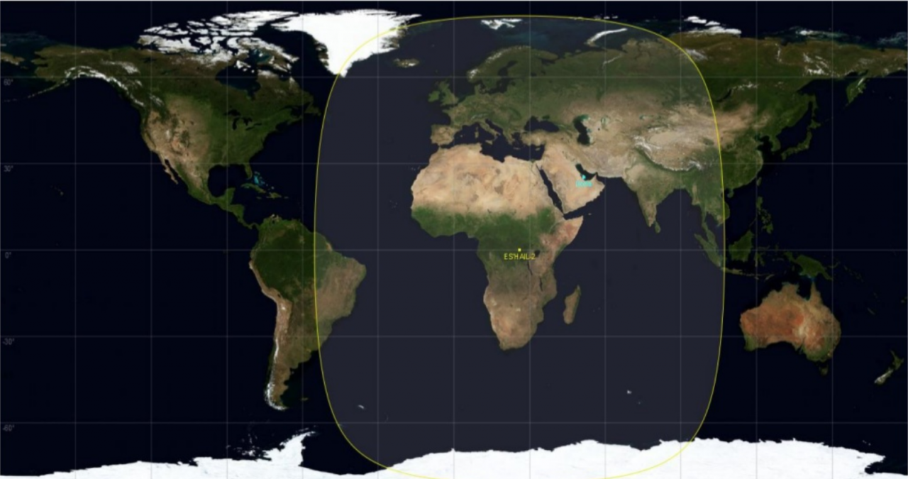
Coverage of the Qatar Oscar 100 satellite
The satellite transponders
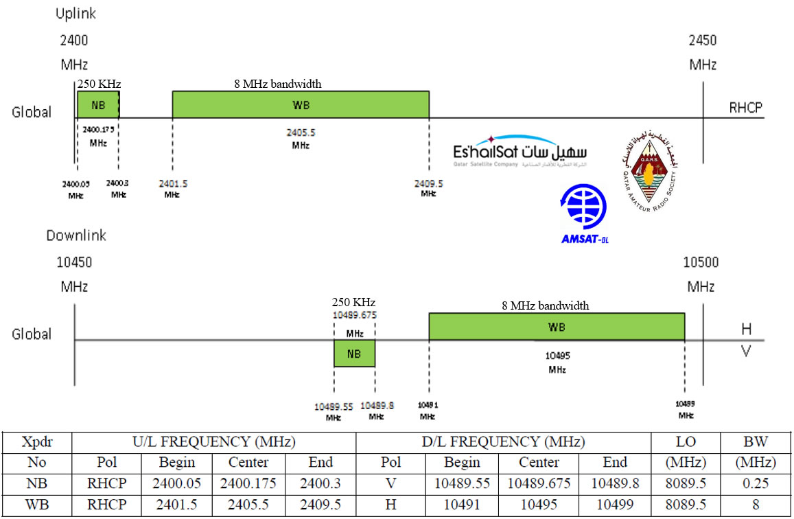
QO-100 fréquences de montées et descentes
The satellite is equipped with two transponders for amateurs:
- A transponder for narrow-band modes (NB: Narrow band)
- A transponder for broadband television transmission (WB: Wide band)
The table below specifies the descent frequencies, which will be received for both transponders. You notice that the two transmissions are not made with the same wave polarization.
| Polarization | Start (MHz) | End (MHz) | Width (MHz) |
|---|---|---|---|
| Vertical | 10489,550 | 10489,800 | 0,250 |
| Horizontal | 10491,000 | 10499,000 | 8,000 |
The diagram
Here is the diagram of the receiving line. It corresponds to one of the ways of receiving the signals transmitted by the QO-100 satellite. It has the advantage of implementing a recent and inexpensive technology, which can be considered to be already equipped with a computer.
As mentioned above, the signal transmitted by the satellite is on 10 GHz, the operation of the head is to convert this frequency into a lower frequency, and therefore more easily usable by the usual receivers.
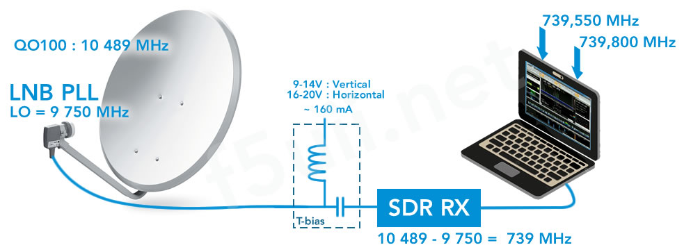
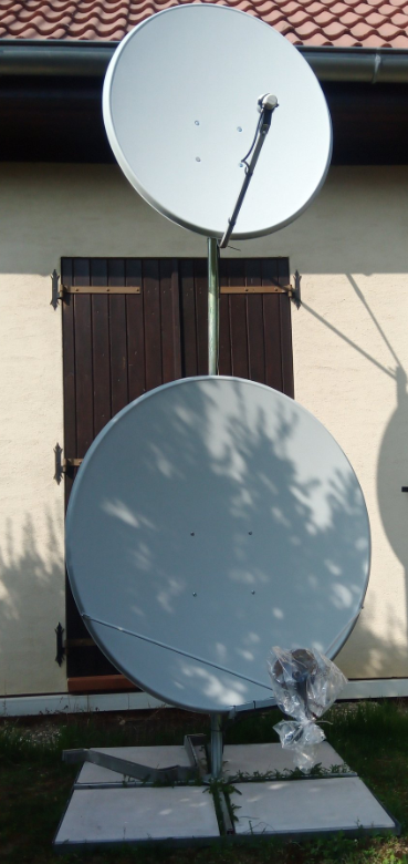
The receiver consists of a dish that focuses the incident signals. In the focal point we will place a LNB television receiver unit. But be careful to choose a LNB (Low Noise Block) with PLL technology (Phase-locked loop also called controlled phase loop). Indeed, LNB satellite with DRO (Dielectric Resonator Oscillator) technology will not be suitable because they have very poor frequency stability. Compared to quartz-based PLL LNBs, DRO is relatively unstable with temperature, and undergoes large frequency fluctuations from +/- 250 kHz to +/- 2 MHz. The PLL LNB will evolve to +/- 25 kHz to +/-50 kHz.
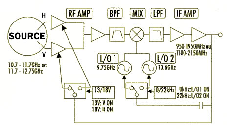
Internal diagram of a satellite LNB
| Power supply voltage | Polarization | Modulation (kHz) | OL (MHz) | Ku band segment (MHz) | Transposed to L-band (MHz) |
|---|---|---|---|---|---|
| 10 à 14 V | Vertical | 0 | 9750 | 10700 à 11700 | 950 à 1950 |
| 15 à 19 V | Horizontal | 0 | 9750 | 10700 à 11700 | 950 à 1950 |
| 10 à 14 V | Vertical | 22 | 10600 | 11700 à 12750 | 1100 à 2150 |
| 15 à 19 V | Horizontal | 22 | 10600 | 11700 à 12750 | 1100 à 2150 |
To operate on the transmission frequency of the QO-100 narrowband transponder, we need to operate the LNB in its low frequency portion. Even if the frequency is lower than the minimum frequency indicated on the LNB manufacturers’ data sheets, the latter will be perfectly suitable. So no need to generate 22kHz, and its power supply will be below 15V to activate vertical polarization. The station power supply you probably already own and which usually supplies 13.8V is therefore perfectly suited to power the head via the T-Bias.
Get the LNB PLL heads
As mentioned above, it is important to choose a PLL LNB. Here are some links that are worth completing as we go along.

T bias power supply

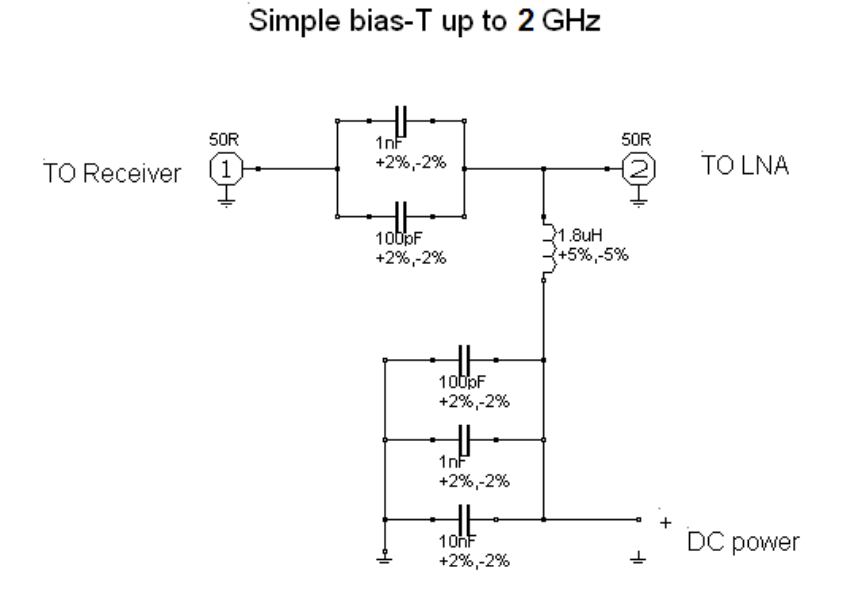
The T-bias is designed to inject direct current into the RF circuit without affecting the RF signal. You can find them all made up or you can of course build them up.
- Bias Tee – 10MHz-6GHz
- T biais 10-6000MHz (aliexpress)
- T bias 10-3000MHz , prise SMA Male / femelle (aliexpress)
- T Bias 10-6000MHz en boitier et SMA fem/fem (aliexpress)
The K6VHF software allows you to calculate the necessary capacitors and inductors.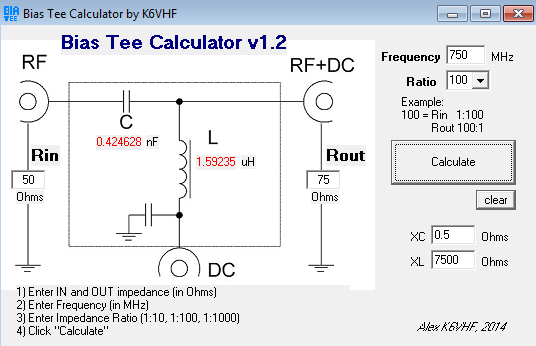


SDR hardware
Le signal va être réceptionné grâce à un “récepteur” SDR (Software Design Radio), qui va transformer le signal en échantillons numériques qui seront récupérés par l’ordinateur. Si vous souhaitez plus de détails sur le fonctionnement des récepteurs et émetteurs SDR, je vous invite vivement à écouter The signal will be received through a SDR (Software Design Radio) “receiver”, which will transform the signal into digital samples that will be collected by the computer. If you would like more details on how SDR receivers and transmitters work, I strongly invite you to listen to Sylvain F4GKR’s presentation which is available on the REF-info channel on Youtube (in french).

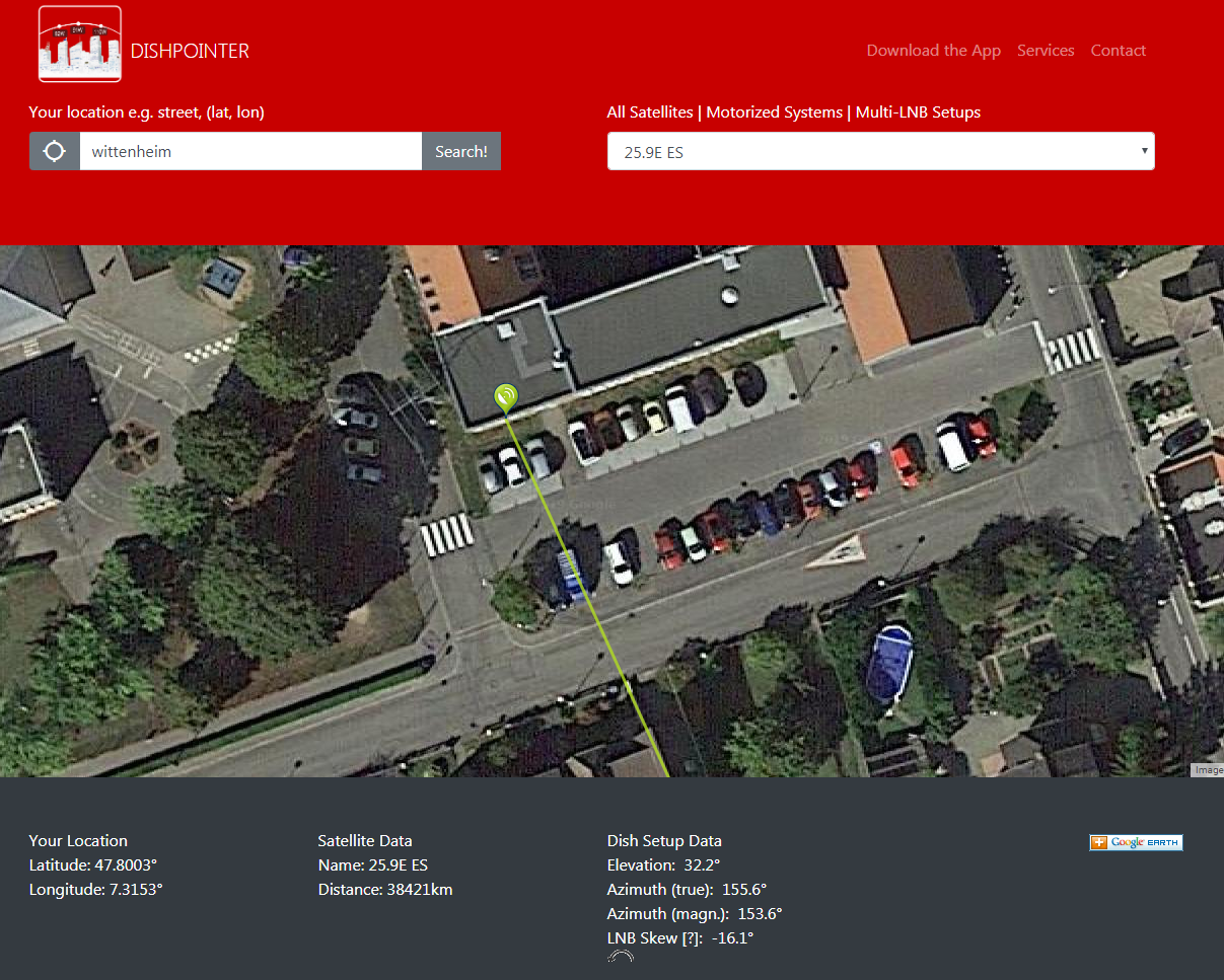
To determine the position of its antenna, it must be pointed as precisely as possible towards the geostationary satellite, positioned at 25.8 degrees East, overhead Kisangani, 35,800 kilometres above the Democratic Republic of the Congo. To help you, you will find below some software on PC, or on smartphone that will help you to do this.
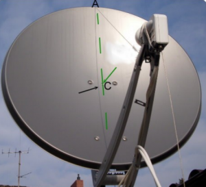
Another solution is to get help from the sun. This web page (french), or this page (french), will tell you at what time the sun is exactly in the direction of the satellite. At this time, you will try to center the shadow of the feed on the vertical axis of symmetry of the dish. You can also help yourself by placing a cord between the bracket and the top of the parabola. Now all you have to do is adjust the elevation, searching directly on your SDR receiver for the strongest signal levels
The third adjustment consists in rotating the LNB unit on itself according to the value of the skew angle.

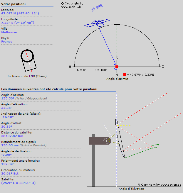
Online software to help with pointing
After indicating your location, and the desired satellite, these websites provide information on the azimuth, elevation and skew angle to be adopted to point the satellite.
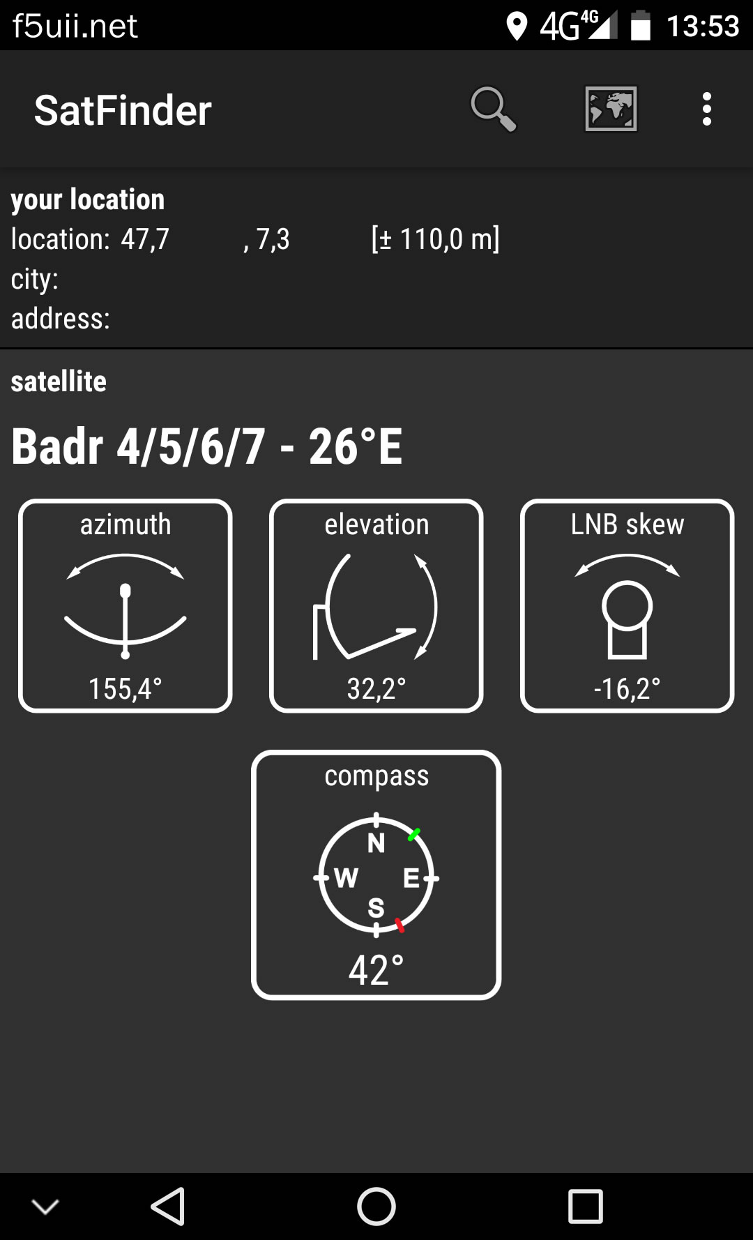
Software for mobile phones
The SDR Console software
The SDR Console software
To use the signals from an SDR stick, we require “processing” software that will allow us to display the received spectrum as well as demodulate the signals. There are several software programs that allow this. What differentiates them, among other things, is the list of supported devices.
For my part, and especially for the reception of the Qatar Oscar 100 satellite, I have chosen to use the “SDR Console” software published by Simon, G4ELI (HB9DRV). It is available in 32 and 64-bit Windows platforms.
SDR hardware supported by SDR Console
The SDR Console software to this day, can manage nineteen hardware products. You can find the complete list on the author’s website on his Supported Radio page.
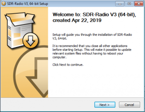
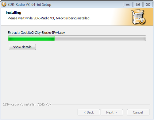
Install the SDR Console software
Download the latest version from the website SDR-Radio.com (version 3.0.7 or later) and start installing the software.


Install your SDR device
At the first launch, the software offers you to search for your SDR devices, which must be connected to your computer.
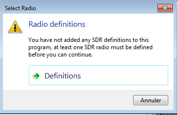

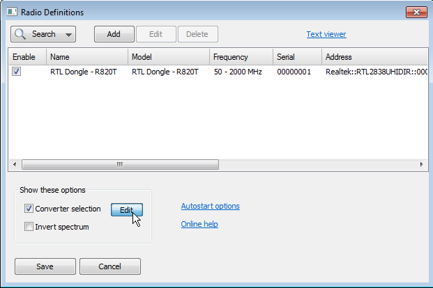
On the Radio Definitions window, click Search to add your device that you have connected to the computer. Here I am looking for the RTL stick. 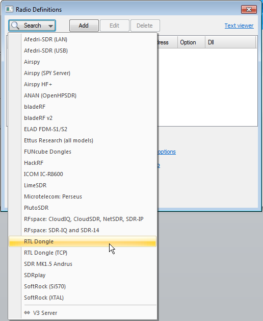

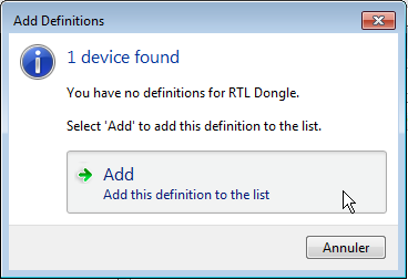
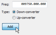
The software confirms that it has found the hardware. I then click on Add.

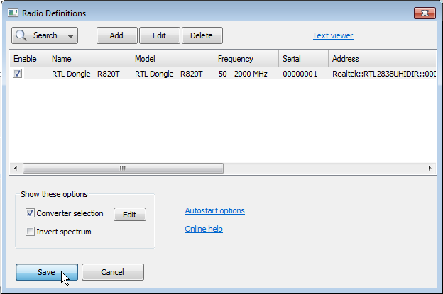
The dongle is then added to my “Radios“. Don’t forget to click on the “Save” button.

Conversion frequencies
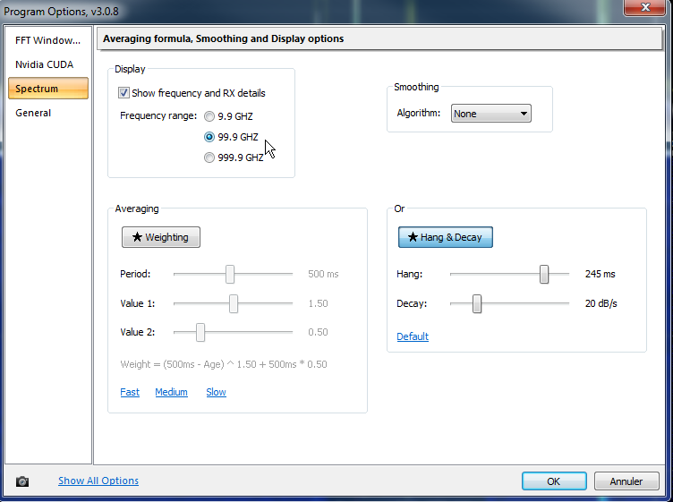
Beforehand, we will ensure that frequencies above 9999 MHz can be displayed without any problems by the software:
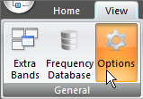
- Click on the View banner then in General on Options
- In the options window, check ‘Show frequency and RX details’ with range = 99.9 GHz, from the Spectrum submenu.


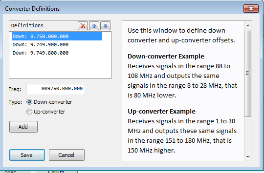
In order to have a direct reading of the satellite frequency (10,489 MHz instead of 749 MHz) after the frequency conversion performed by the LNB, we will indicate to the SDR Console software the frequency of 9750 MHz, which is the conversion frequency of the LNB oscillator.
In the “Radios” hardware definition window, click on the Edit button positioned after the “Converter selection” line.

We will now enter the conversion frequency as 009750.000.000.000 and check Down-converter.

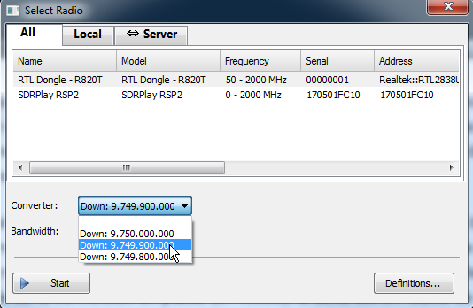
Don’t forget to click on the Save button to save your entry. Here, I entered several frequencies, close to 9 750MHz. The reason is explained below.

Start reception
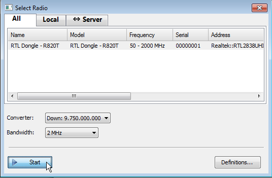
After connecting the cable to your T-bias and dish to your SDR receiver, we will start receiving with SDR Console. Select the radio, as well as the frequency of the ‘Converter‘. Click on ‘Start‘.

The reception stabilization option
Since version 3.0.7, the SDR Console software has included a very practical reception stabilization feature. Indeed, the LNB PLL drifts slightly depending on the temperature evolution. Simon G4ELI has developed a software system for controlling the reception window by referring to the modulated BPSK beacon located at the end-of-band of the transponder. The beacon frequency is known and fixed at 10,489,800 MHz.
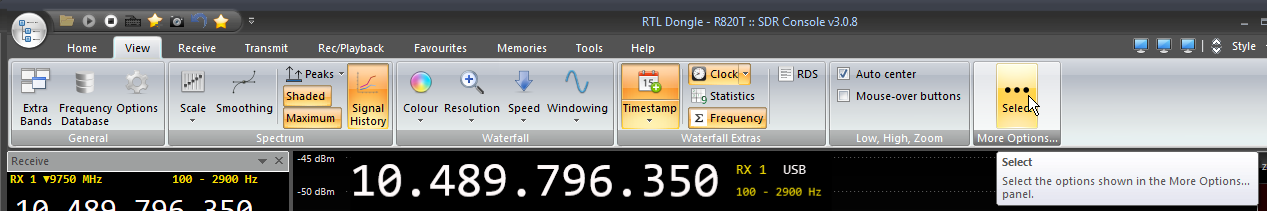
We will immediately start the SDR Console option which allows the frequency stabilization: In the “View” tab, click on Select of the “More options…” button.

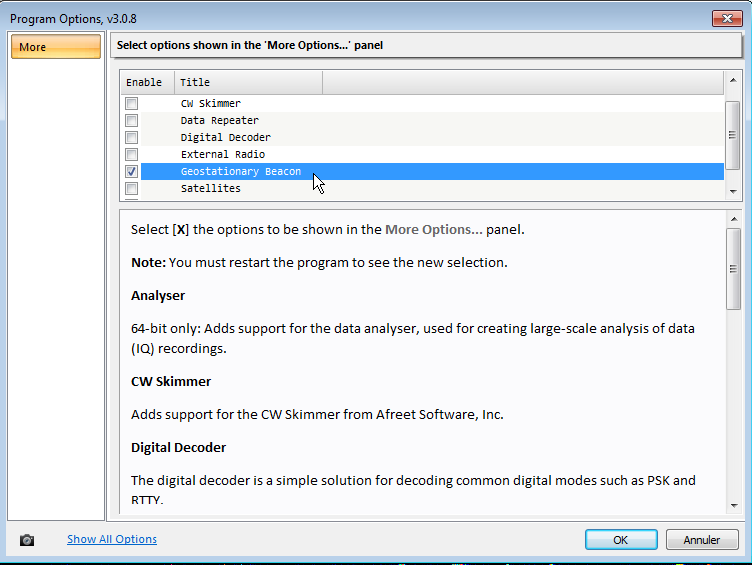
Check the line “Geostationary Beacon” and confirm with OK.

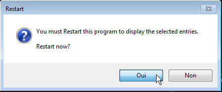
Restart SDR Console.

The feedback window to the BPSK beacon of QO-100
Return to the View tab and now click on the ‘Geostationary Beacon‘ button
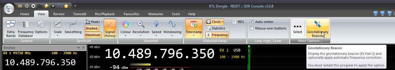

At the bottom of the screen is the window “Geostationary Satellite Beacon“.
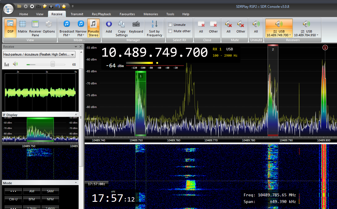
- Start the waterfall of the Geostationary Satellite Beacon screen, by clicking on the first Start button (the circle)
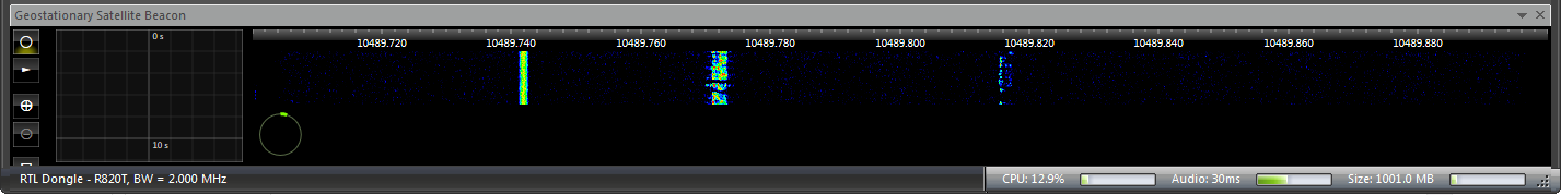

You should see the upper band beacon modulated in BPSK. If, as in the above capture, you do not see this QO-100 beacon, this means that your LNB has a frequency difference too high for display the beacon in the 10489700 – 10489900 range proposed by SDR Console. To display the BPSK beacon, you will then need to add different conversion frequencies (reduced or increased) to the list of Down Converters, as presented above in the text.

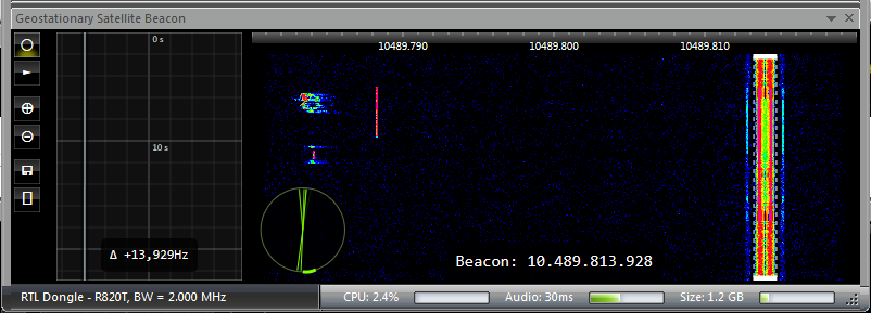

3. To start the frequency correction, click on the second Enable button on the side band. The button is active (highlighted). The entire spectrum is then automatically adjusted by SDR Console to place the beacon at its fixed frequency of 10 489 800 kHz, whatever the real drift that the entire spectrum is undergoing due to the drift of the LNB.
![]()

When SDR Console is launched in the future, you will no longer have to perform steps 1 and 2, but only step 3 to select the BPSK beacon and launch the locking feature (click on Enable)
SDR Console with QO-100 reception stabilization
In addition to the stabilization feature itself, the SDR Console software also allows (and as an accessory, it is true) to export the correction points that the software has bring. So we will be able to see the evolutions of frequency that the LNB has “caused ” to the software….
To accomplish this,
- Click on the button that represents the floppy disk.

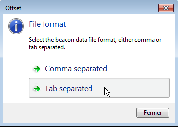
- Choose the output format of the file (here Tabulations separator)
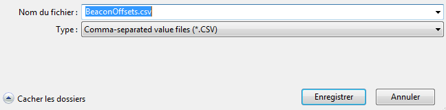
- Save your file in the desired location on your computer
- Click on Open file to open the file directly through your usual spreadsheet software
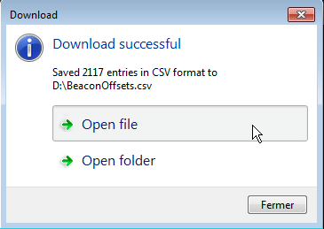
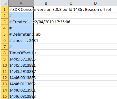
- If you use Excel, you will find a sheet, in which you can find up to 10,000 samples.
- We can quickly create a graph to represent the frequency evolution generated by the LNB oscillator. First, we need to reconstruct the data under two columns. Select column A (click on the letter A)
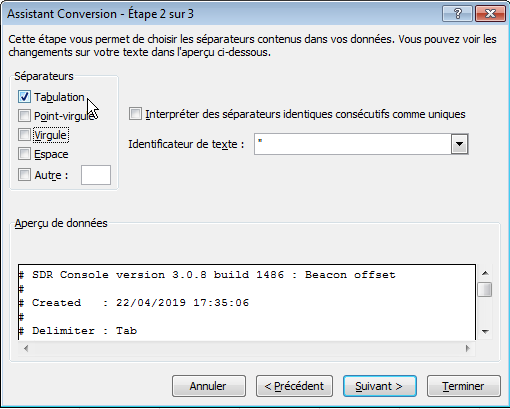
- In Office Excel 2010 (or newer), select Data and then Convert. Choose the data type Delimited. Then check Tabulation, and click Finish. This creates two columns in the Excel table.


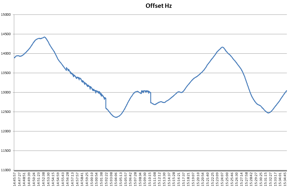
Now select your two columns with the Time and Offset headers. Click on Insert, and choose a line graph template. The result is displayed and shows the frequency correction work performed by the SDR Console software.

Multiple receiving
The SDR Console software is designed to receive several frequencies simultaneously. This allows a second frequency to be monitored… possibly in another mode.
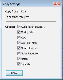
To add a receiver, on the Receive menu, click on Add. You can copy the settings of your active channel to the other channels by pressing the’Copy Settings‘ button.


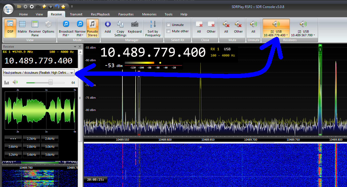
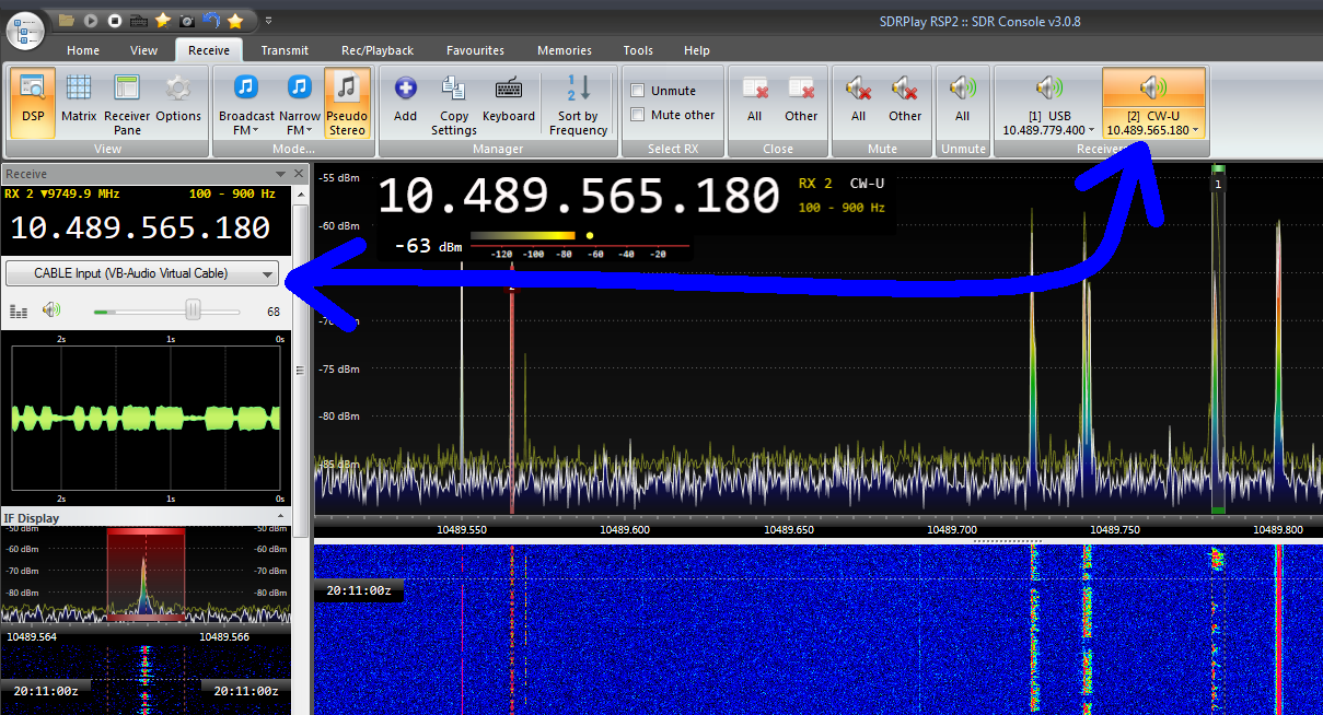
From the Receive / Receivers tab, you can activate several receivers simultaneously or switch off the reception of one or the other of the receivers.
For example, we can have a receiver dedicated to SSTV reception that sends its audio signal to a virtual sound card, which will be used by the SSTV image decoding software, while we also receive voice via USB. Below, a signal is voice, the second is morse code which could be decoded in parallel by another software (CW skimmer for example).


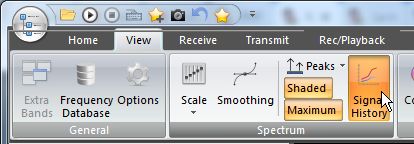
The signal strength history
A SDR Console banner displays the strength of the signals of the receiving channel. To activate it, click on Signal History on the View tab.

The pseudo-stereo
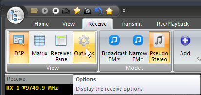
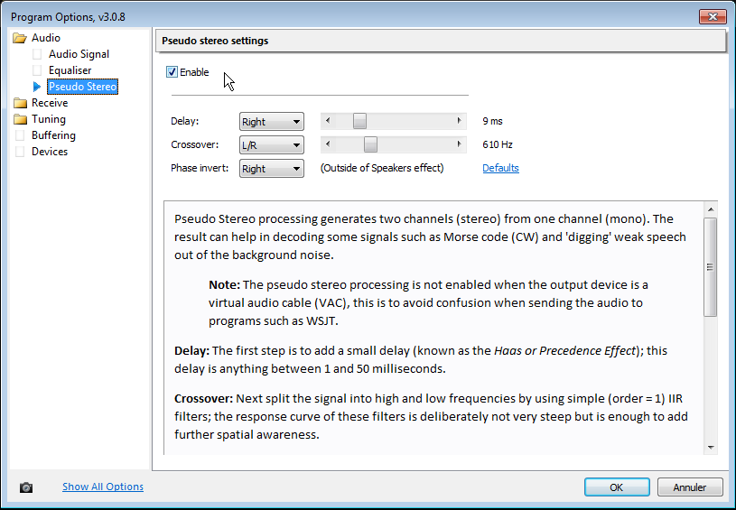
The SDR Console software includes a function that Elecraft K3 transceiver users are familiar with. This is a function that creates a stereo audio signal from the mono stream; this is achieved by generating a delayed signal. It can be adjusted as you wish from the Receive / Options menu, then in the Audio / Pseudo Stereo submenu. Check Enable to activate it.


Here is an example of an audio recording made with the Pseudo stereo feature of SDR Console (you will hear F1AZF, Eric from department 52 in JN28NJ).
The quality of the audio playback is all the more interesting when using an audio headset. In the case of this recording, the NR1 DSP filter is active and set to 6dB.
The same receiving line will be used to receive digital television images transmitted on the second QO-100 transponder, the 8MHz wideband transponder.
To do this, you must switch the reception polarization of your LNB to horizontal. For this purpose, you will supply the LNB with between 15 and 20 Volts, in accordance with the LNB’s characteristic sheet.
In place of the SDR reception equipment and the SDR Console software, I recommend the implementation of the DATV receiver board designed by the French OMs F6DZP, F1TE : The Minitiouner Pro and its Minitiouner software.

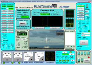
Software Minitioune V0.9 beta7, with the 2000 SR QO-100 video beacon

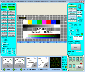
Helmut DG3KHS in 1000 SR via QO-100
I do not develop this subject in this article at this time. But for now, I invite you to find all the useful information about DATV on these websites.
- Viva DATV forum : www.vivadatv.org
- REF shop : boutique.r-e-f.org
- DATV transmissions on broadband live : eshail.batc.org.uk/wb/

Feel free to share your experiences, remarks by using directly the comments below. I would like to inform you that for your technical support needs, this is achieved only through public comments directly on this page, so that all readers can contribute to it. No support by private contact will be provided.
Very good listening of satellite communications on Es’hail 2 / Phase 4A / Qatar Oscar 100 !
References
LNB diagram: Telesatellite.com