L'amplification de signaux sur 2,4GHz
The amplification line
Now, I propose to focus on the transmission and amplification equipment, individually.
First element, the SDR transmitter
As indicated in the introduction, I only deal here with the case of an SDR transmitter. The power considerations obviously remain the same for a conventional up-converter transmitter.
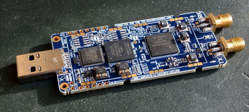
LimeSDR mini
The LimeSDR is an open-source SDR receiver and transmitter USB stick, to be connected to a microcomputer, and covering frequencies from 10MHz to 3.5GHz (for the LimeSDR mini and LimeNET-Micro version) or from 100kHz to 3.8GHz (for the LimeSDR version) and operates in full duplex (simultaneous reception and transmission). Its maximum output power measured at the output of LimeSDR mini is 3 dBm (2mW).
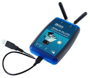
Adalm Pluto Emetteur/Récepteur SDR
Other SDR transmitters / receivers are possible, such as Adalm Pluto from Analog Device (Amazon Link). A modification to improve stabilization is required for narrowband transmission (SSB). I invite you to refer to this modification of the Adalm Pluto of Lucien F1TE’s french article which concerns the replacement of the cristal by a TCXO whose temperature derivation is compensated. Another alternative is to provide a stable 40 MHz reference signal using a GPSDO (GPS disciplinated oscillator) generator
These SDR transmitters can be used for narrowband transmission but also as a broadband transmitter for DATV digital television (Maybe the subject of another article later ?).
Filtering
Before mentioning filters, I would like to recall some points of the regulations concerning the amateur band 2300 – 2450 Mhz. The amateur-satellite service may operate in the bands 435-438 MHz, 1260-1270 MHz, 2400- 2450 MHz, provided that this does not result in harmful interference to other user services. In these bands, the amateur service has a secondary status and any harmful interference caused by satellite emissions must be immediately eliminated (RR provision S5-282). As a reminder, the maximum transmitter output power is 120W (50.8dBm).
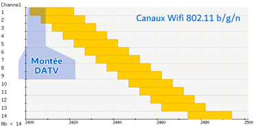 On the 2400 MHz band part, we will find public uses such as bluetooth and wireless networks Wifi 802.11b/g/n. It is therefore important that spurious emissions are properly rejected at low levels, and at least to those expected by the regulations [ APPENDIX 3 of the Radio Regulations for ground satellite stations: 43 + 10 log (P) or 60 dBc minimum]
It is therefore advisable not to drive the amplifier circuits into their non-linear operating area and to complete the stations, especially SDR, with a 2400 MHz band pass filter after the transmitter.
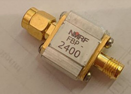
- A cheap filter exists on the Asian reseller market: the 2400 NMRF FBP-2400, with significant losses (4dBm) on 2400 Mhz and its Return Loss -20 dBm (SWR 1.2) Links. Links Aliexpress ou ebay.
-
- A second one is available in Canada, and sold by GPIO Labs: 2450 GPIO LABS. These losses are less significant (2.4dBm) for the same RL than the previous one. Link to Ebay.
-
- There are other more professional filters where losses are reduced:ID-Elektronik in Germany
- For do-it-yourselfers, there is a solution that consists in building a resonant cap “Pipe-cap filter”
- KO4BB
- 9A4QV
- W1GHZ (complete documentation Pipe-cap_Filters_Revisited by W1GHZ.pdf)
The preamplification
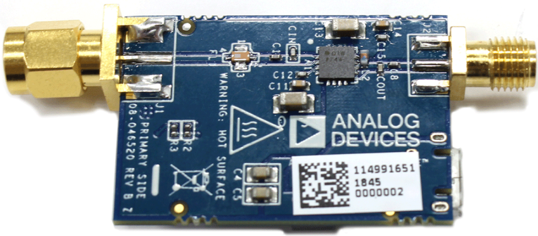
Analog Device CN0417
On the diagram, after the transmitter, you will find a pre-amplification stage for the signal. In this diagram, it is a CN0417 board from Analog Device that is equipped with a two-stage, 1W, two-stage ADL5606 wideband amplifier (see ADL5606 datasheet), which operates over a frequency range from 1800 MHz to 2700 MHz. It integrates an in-line band-pass filter and will provide a 30dBm level output with the LimeSDR mini thanks to its real gain of 20 dB on 2400 MHz. It is powered by a micro-USB plug. Its maximum input level is 18 dBm.
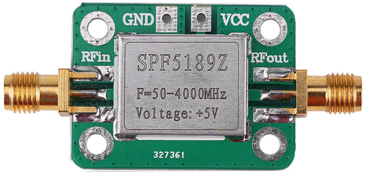
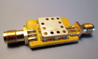
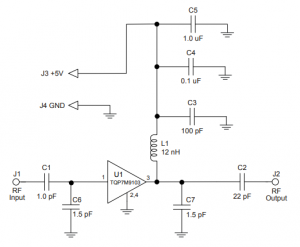
SPF5189Z
Second possibility. The SPF5189Z is a 5V powered preamp that offers 8 to 11 dBm of gain. You will find a detailed measurement report on the Matthias DD1US website. My measurements give me 11 dBm of gain on 2400 MHz. According to the SPF5189z datasheet, the maximum acceptable input is 27 dBm. You can therefore completely cascade two preamplifiers, one after the other. The Chinese reseller market offers them for less than 5 EUR (link SPF5189Z Ebay, link SPF5189Z Aliexpress).
Bonjour Christian,
Superbe travail…Bravo et merci de faire partager.
Je voudrais démarrer sur QO-100 sans aucune expérience satellite (OM).
J’ai compris que dans votre description de la partie réception, vous utilisiez un dongle RTL mais qu’ensuite lorsque vous décrivez la partie émission, vous utilisez un transceiver Lime SDR pour l’émission et la réception.
– Je ne comprends pas bien quels sont les éléments de la photo ci-dessus..?
– a priori le mode de fonctionnement est le full-duplex mais je ne vois pas comment il est possible de connecter simultanément la sortie de la tête 10GHz et l’antenne hélice d’émission via les différents preamplis et amplis mentionnées.
Merci pour votre aide.
Gérard
F6EHJ/FY7BC
(Translation)
Hello Christian,
Great work…Well done and thank you for sharing.
I would like to start on QO-100 without any satellite experience (OM).
I understand that in your description of the reception part, you use an RTL dongle but then when you describe the transmission part, you use a Lime SDR transceiver for transmission and reception.
– I don’t quite understand what the elements of the picture above are…?
– a priori the operating mode is full-duplex but I don’t see how it is possible to connect simultaneously the output of the 10GHz head and the transmission propeller antenna via the different preamps and amplifiers mentioned.
Thank you for your help.
Gérard
F6EHJ/FY7BC
Gérard,
Sur la photo de la page 6, on voit le LimeSDR dans un boitier noir (impression 3D). A gauche le connecteur SMA servant à la voie de réception (le T-bias n’est pas sur la photo), et à droite celle servant à la voie d’émission. Connecté, il y a le module CN-0417 (et son filtre intégré) alimenté en micro-USB, suivi ensuite de l’ampli chinois de 2.5W (à droite en noir). L’antenne y est connecté en bas.
Cela correspondant au diagramme de la page 3 à lire de droite à gauche.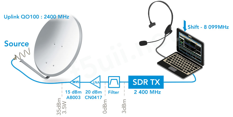
73 Christian
(Translation)
Gerard,
On the picture on page 6, we see the LimeSDR in a black box (3D printing). On the left the SMA connector used for the reception channel (the T-bias is not in the picture), and on the right the one used for the transmission channel. Connected, there is the CN-0417 module (and its built-in filter) powered by micro-USB, followed by the Chinese 2.5W amp (right in black). The antenna is connected to it at the bottom.
This corresponds to the diagram on page 3 to be read from right to left.
73 Christian
Merci Christian,
Je vous ai entendu sur le web SDR.
Je déchiffre la doc et il y en a..!
Je vais partir sur un LimeSDR mini que j’aimerai bien faire tourner sous Mac OS ou Raspberry mais pour le PI je n’ai pas vu grand chose pour la bande étroite mais plutôt pour DATV.
A suivre
73
Gérard
(Translation)
Thank you Christian,
I heard you on the web SDR.
I decipher the doc and there are some…!
I’m going to start on a LimeSDR mini that I’d like to run on Mac OS or Raspberry but for the PI I didn’t see much for the narrowband but rather for DATV.
To be continued
73
Gérard
Gérard,
LimeSDR mini est exploitable en émission et réception avec le logiciel SDR Angel de F4EXB (https://github.com/f4exb/sdrangel) sous Linux
Il y a également GQRX qui pourrait être une solution (A vérifier si l’émission est supportée).
Par contre, coté Mac OS, je ne sais pas y répondre personnellement.
Bons essais, et à bientôt sur le satellite alors…
73 Christian
(Translation)
Gerard,
LimeSDR mini can be used in transmission and reception with F4EXB’s SDR Angel software (https://github.com/f4exb/sdrangel) under Linux
There is also GQRX which could be a solution (To check if the transmission is supported).
On the other hand, on the Mac OS side, I don’t know how to answer it personally.
Good tests, and see you soon on the satellite then….
73 Christian
Merci Christian pour ce superbe article, très bien fait (et en français…) qui devrait inciter beaucoup d’om, à trafiquer via QO-100.
Une petite question: dans SDRConsole (pour Lime Mini), dans la petite fenêtre en bas à gauche “Radio”, il y a un bouton “RX Ant” avec différentes valeurs LNA comme ” LNA_NC”. A quoi ça correspond, à: non connecté? que faut-il mettre ?
(Translation)
Thank you Christian for this superb article, very well written (and in French…) which should encourage a lot of om, to work via QO-100.
A quick question: in SDRConsole (for Lime Mini), in the small window at the bottom left “Radio”, there is a button “RX Ant” with different LNA values like “LNA_NC”. What does it mean, not connected? What should I put in ?
Merci Robert pour les encouragements.
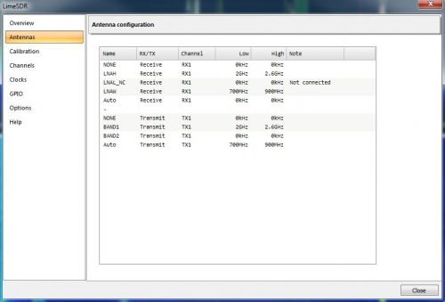
La carte LimeSDR-Mini couvre la gamme de fréquences RF de 10MHz à 3.5GHz. Il existe différents réseaux d’adaptation connectés aux entrées et sorties RF de l’émetteur-récepteur RF (antennes) :
Je pense que les noms des réseaux actuellement indiqué dans SDR console corresponde plutôt à ceux LimeSDR USB. ‘est pourquoi l’un deux est NC pour LNAL (non connecté). Les informations trouvés pour le LimeSDR USB :
En cliquant sur le bouton |…|, on trouve ces définitions.
Je vous invite à lire les échanges sur ce point sur le forum MyriadRF
https://discourse.myriadrf.org/t/rf-connection-10-u-fl-connectors-6-rx-4-tx/305/49
https://discourse.myriadrf.org/t/limesdr-mini-antenna-gain-modes-none-lnal-nc-lnah-and-lnaw/2779
(Translation)
Thank you Robert for the encouragement.
The LimeSDR-Mini board covers the RF frequency range from 10MHz to 3.5GHz. There are different adaptation networks connected to the RF inputs and outputs of the RF transceiver (antennas):
I think that the network names currently indicated in SDR console correspond rather to those of LimeSDR USB. Therefore, one of them is NC for LNAL (not connected). The information found for the LimeSDR USB:
By clicking on the button |….|, you can find these definitions.

I invite you to read the discussions on this point on the MyriadRF forum
https://discourse.myriadrf.org/t/rf-connection-10-u-fl-connectors-6-rx-4-tx/305/49
https://discourse.myriadrf.org/t/limesdr-mini-antenna-gain-modes-none-lnal-nc-lnah-and-lnaw/2779
Bonjour Christian,
Bravo et merci pour ce superbe article pour s’équiper pour trafiquer sur QO-100.
Une petite question: J’ai fait l’acquisition d’un milliwattmètre 1 à 8000Mhz à base d’un module RF AD8318
de -55 dbm à – 5dbm.
Pouvez-vous m’indiquer comment je peux télécharger le logiciel pour piloter ce milliwattmètre.
Merci et 73 de F4FZQ.
(Translation)
Hello, Christian,
Congratulations and thank you for this great article to equip ourselves to work on QO-100.
A quick question: I acquired a milliwattmeter 1 at 8000Mhz based on an AD8318 RF module, from -55 dbm to -5dbm.
Can you tell me how I can download the software to drive this milliwattmeter.
Thank you and 73 from F4FZQ.
Bonjour Jean-Claude,
Heureux de savoir que le contenu de ce site vous satisfasse.
Vous avez fait le choix d’une platine AD8318 programmable, alors qu’il en existe certaine version équipé de clavier et écran.
Je vous invite à visualiser cette vidéo très didactique sur ces puissance-mètres. L’exemple est réalisé avec un STM32 mais peut l’être avec un arduino. Des ressources de codes sont également rendus disponibles par DL2DBA. A priori, vous pourriez mettre en oeuvre un écran tactile comme le montre SV1AFN
Bon bricolage, 73
Christian
(Translation)
Hello, Jean-Claude,
Glad to know that you are satisfied with the content of this site.
You have chosen a programmable AD8318 turntable, although there are some versions available equipped with keyboard and screen.
I invite you to watch this very didactic video about these power meters. The example is made with a STM32 but can be made with an arduino. Code resources are also made available by DL2DBA. in principle, you could implement a touch screen as shown in SV1AFN
Good DIY, 73
Christian
Merci Christian pour votre réponse,
Le milliwattmètre que j’ai commandé est le module équipé d’un clavier et d’un écran avec un cordon USB,
mais le vendeur n’a pas fourni la notice d’emploi ni le logiciel, le matériel est donc inutilisable.
Je vais continuer mes recherches.
Merci et 73 Christian.
Jean Claude.
F4FZQ.
(Translation)
Thank you Christian for your answer,
The milliwattmeter I ordered is the module equipped with a keyboard and a display with a USB cord,
but the vendor has not provided the instruction manual or software, so the hardware is unusable.
I will continue my investigations.
Thank you and 73 Christian.
Jean Claude.
F4FZQ.
Très bien, s’il s’agit du modèle avec clavier et écran. Son usage n’est pas compliqué. Les distributeurs ne fournissent que très rarement de la documentation.
Je vous propose de télécharger le logiciel qui permet le piloter le powerMeter RF 8000 MHz depuis un PC windows.
73
(Translation)
Fine, if it’s the model with the keyboard and monitor. It’s not complicated to use. Distributors rarely provide documentation.
I propose you to download the software that allows you to drive the 8000 MHz RF powerMeter from a windows PC.
73
Salut Christian
Merci infiniment !! pour vos articles trés instructifset méthodiques, j’ai juste une petite question concernant le dernier étage d’amplification (amplificateur chinois).Selon vos images partagées sur votre montage vous avez choisi EDUP AB007, boite étiquetée 4W.A présent vous avez bien expérimenté ces ampli chinois qu’est vous recommendez ?
Meilleurs Salutations 73
(Translation)
Hi, Christian.
Thank you very much for your very instructive and methodical articles, I just have a small question about the last stage of amplification (Chinese amplifier). According to your shared pictures on your editing you chose EDUP AB007, box labeled 4W. Now you have experienced these Chinese amplifiers what do you recommend?
Best regards 73
Bonjour a tous, pouvez vous m’expliquer pourquoi je n’ai pas d’émission avec mon lime sdr cela fonctionnait avant que je ne reformate tous le pc, la réception est ok cela fonctionne bien en réception tout semble ok mais quand je tune ou que je parle dans le micro rien ne ce passe je vois bien le spectre de mon micro fonctionner, j’ai mis les drive au maxi, mon amplificateur AB007 ne change pas d’état la led reste rouge et ne passe pas au vert, je suis en version 3.0.21.
Quelqu’un peux t’il m’aiguiller merci
(Translation)
Hello everyone, can you explain me why I don’t have a transmission with my limesdr, it was working before I reformat all the pc, the reception is ok it works well in reception everything seems ok but when I tune or I talk into the microphone nothing happens I can see the spectrum of my microphone working, I put the drives at maximum, my amplifier AB007 does not change state the led remains red and does not go to green, I’m in version 3.0.21.
Can someone please give me directions, thank you.
Re-Bonjour. Après moult essais l’émission à l’air de fonctionner la led de l’ampli passe au vert j’ai mis comme Converter 9750.135 TX et 8099 en RX
Mais apparemment je n’émets pas sur la fréquence que j’écoute je vois une pointe quand j’émet qui semble être la mienne.
(Translation)
Hello again. After many tests the air emission of the amp’s led is green I put as Converter 9750.135 TX and 8099 in RX
But apparently I’m not transmitting on the frequency I’m listening to, I see a spike when I transmit that seems to be mine.
Bonjour Thierry,
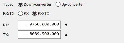
Content de savoir que votre émission fonctionne. En effet les valeurs de shifts ne sont pas les bons. Je vous invite à modifier les valeurs : 9750.000 et 8089.500
Au plaisir d’un prochain QSO sur QO-100 ! 73 F5UII
(Translation)
Hello, Thierry,
Glad to know your show is working. Indeed the shifts values are not the right ones. I invite you to change the values: 9750,000 and 8089,500.

Looking forward to the next QSO on QO-100! 73 F5UII
Bonjour et merci a vous pour ces réponses apparemment cela fonctionne mais j’attends mon micro USB pour finaliser.
malgré tout quand je lance un tune je vois bien le pic ce faire mais il est plusieurs fois sur le spectre et beaucoup plus fort décalé de 300hz plus bas et pas entre les deux lignes vertes .
comment faire pour déjà quand je suis sur la balise, je suis sur 10 489.772 avant de faire le geostationary beacon apres je suis sur 10.489.748 quand je fais un tune sur cette fréquence je vois bien mon pic mais aussi sur10 489.500 et l’Émission est plus forte.Il doit y avoir un décalage.
merci de votre aide.
(Translation)
Hello and thank you for your answers. Apparently it works but I’m waiting for my USB microphone to finalize.
I’m waiting for my USB microphone to finalize it. When I play a tune I can see the peak but it is several times on the spectrum and much stronger 300hz lower and not between the two green lines.
how to do for already when I am on the beacon, I am on 10 489.772 before doing the geostationary beacon after I am on 10.489.748 when I make a tune on this frequency I can see my peak but also on 10 489.500 and the emission is stronger. there must be an offset.
Thank you for your help.
Votre LNB n’est décalé de 22 kHz, et donc assez proche de la bonne fréquence. C’est très correct.
Oui en démarrant la stabilisation de la réception, le spectre se positionne de façon à ce que la balise centrale soit positionnée sur 10 489 750. Tout d’abord, vous ne devez pas émettre sur les balises (toujours avoir 5 kHz de garde).
Par contre le décalage entre la monté et la descente que vous indiqué serait de 250 kHz est incompréhensible, si vous avez bien indiqué en TX converter 8089.5
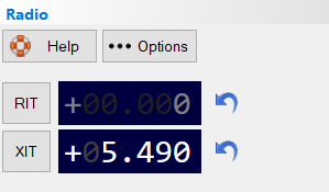
Toutefois pour corriger les quelques Hz ou khZ entre émission et réception, vous aller pouvoir utiliser le XIT (sur la panneau Receive). Enclencher le bouton XIT et régler ou saisir la valeur de correction.
Votre LNB n’est décalé de 22 kHz, et donc assez proche de la bonne fréquence. C’est très correct.
Oui en démarrant la stabilisation de la réception, le spectre se positionne de façon à ce que la balise centrale soit positionnée sur 10 489 750. Tout d’abord, vous ne devez pas émettre sur les balises (toujours avoir 5 kHz de garde).
Par contre le décalage entre la monté et la descente que vous indiqué serait de 250 kHz est incompréhensible, si vous avez bien indiqué en TX converter 8089.5
Toutefois pour corriger les quelques Hz ou khZ entre émission et réception, vous aller pouvoir utiliser le XIT (sur la panneau Receive). Enclencher le bouton XIT et régler ou saisir la valeur de correction.
Bon trafic
(Translation)

Your LNB is only 22 kHz off-set, and therefore quite close to the right frequency. This is very correct.
Yes by starting the reception stabilization, the spectrum is positioned so that the central beacon is positioned on 10 489 750. First of all, you must not transmit on the beacons (always have 5 kHz guard).
On the other hand, the offset between the up and down that you would indicate would be 250 kHz is incomprehensible, if you have correctly indicated in TX converter 8089.5
However to correct the few Hz or khZ between transmission and reception, you will be able to use the XIT (on the Receive panel). Press the XIT button and set or enter the correction value.
Good trafic
bonjour,
après plusieurs essais sans micro mais avec le tune le décalage est toujours présent j’ai fais une petite vidéo mais je ne sais pas comment la mettre pour avoir un avis.
merci de me dire comment je peux faire cela
merci encore
(Translation)
Good morning,
after several tries without microphone but with the tune the gap is still present. i made a small video but i don’t know how to put it to get an opinion.
thanks for telling me how I can do this
thanks again
Bonjour Thierry,
Avec les 2 méthodes complémentaires déjà indiquées, il n’y a pas de raison à priori de ne pas réussir à faire coïncider votre émission à la descente de réception. Il vous faut la dernière version de SDR Console qui exploite la nouvelle fréquence 10 489 750 de la balise BPSK (depuis 14/02/2020) qui sert au positionnement votre réception. Si toute fois vous voulez partager une vidéo, je vous invite à utiliser l’un des hébergeurs comme streamable.com
73 Christian
(Translation)
Hello, Thierry,
With the 2 complementary methods already indicated, there is no reason in principle why your transmission should not coincide with the downlink. You need the latest version of SDR Console which exploits the new frequency 10 489 750 of the BPSK beacon (since 14th feb 2020) which is used to position your reception. If you still want to share a video, I invite you to use one of the hosts like streamable.com
73 Christian
merci de ces réponses mais toujours le mème problème je joint la vidéo en espérant que cela va marcher merci.
De plus de temps en temps il y a des freeze de peu de temps parfois il boggue
la config est pourtant costaud ryzen 5 x2600 carte mère x470 asus
16 giga de memoires dois je mettre plus
Merci
(Translation)
thank you for these answers but still the same problem I attach the video hopefully it will work thanks.
Also from time to time there are short freezes sometimes it bugs
the config is however strong ryzen 5 x2600 motherboard x470 asus
16 gigabytes of memory should I put in more.
Thank you
Thierry, je constate que vous n’avez pas suivi toute les étapes de mon tutoriel. Pour corriger vous devez
Bons réglages.
(Translation)
Thierry, I see that you did not follow all the steps of my tutorial. To correct you must
Good settings
Bonjour ,
Étant tenace quand même j’ai tout recommencer ce matin déjà par la réception j’ai recaler la parabole pour voir si il n’y a pas de problème nickel je précise que pour régler j’ai un satlink et je suis ok j’ai refais l’instal de sdr console réinstaller les drivers la carte est bien reconnu en réception cela fonctionne impec.
j’ai regarder le ros de mon antenne hélice 1.4 avec mon N1201SA j’ai mis le down converter, comme je ne voyais pas la balise j’ai mis 9750.01 et 809505 pour l’émission, j’ai mis la balise avec geostationary
quand je fais un tune je ne vois rien sur l’écran je me suis mis sur 10489.710 j’ai mis websdr sur 10489.709.79 refais un tune et la je vois et j’entends mon tune sur la bonne fréquence.
je pense que je n’ai pas assez de puissance qu’en pensez vous.
De plus par moment le sdrconsole s’arrete une fraction de seconde et repart quelqun peut il m’expliquer je vous met mon email si quelqun est equipe comme moi j’aimerais m’entretenir avec lui pour avoir plus d’explication merci à ceux qui voudrons bien me donner un coup de main F5PLS1@WANADOO.FR je lui donnerais mon tel.
(Translation)
Hello,
Being tenacious, I started again this morning already by the reception I have adjusted the dish to see if there is no problem nickel I say that to fix I have a satlink and I’m ok I redo the installation of sdr console reinstall the drivers the card is well recognized in reception it works impeccably.
I looked at the ros of my antenna helix 1.4 with my N1201SA I put the down converter, as I could not see the beacon I put 9750.01 and 809505 for the transmission, I put the beacon with geostationary
when I make a tune I don’t see anything on the screen I put myself on 10489.710 I put websdr on 10489.709.79 redo a tune and there I see and hear my tune on the right frequency.
I think I don’t have enough power as you think.
Moreover by moment the sdrconsole stops a fraction of a second and restarts someone can it explain me I put my email if someone is equipped like me I would like to speak with him to have more explanation thank you to those who will give me a helping hand.
Bonjour Christian,
D’abord merci pour ce super travail et pour le partage.
J’ai installé SDR-CONSOLE v3.0.22 avec un Limesdr mini.
J’ai configuré la réception avec le rattrapage de fréquence. J’ai testé différents réglages et cela fonctionne correctement.
Par contre dans la fenêtre des options de la partie émission je ne ne vois pas apparaître la ligne Frequency offset. Donc impossible d’activer le décalage entre réception et émission.
J’au du rater quelque chose ou peut-être une modification dans les nouvelles versions du logiciel depuis votre article.
Merci pour votre aide.
Amicalement
jean-Louis F5NXG
(Translation)
Hello, Christian,
First of all, thank you for the great work and for sharing.
I installed SDR-CONSOLE v3.0.22 with a Limesdr mini.
I have configured the reception with the frequency catch-up. I tested different settings and it works fine.
However, in the options window of the transmission part I don’t see the line Frequency offset. So it is impossible to activate the offset between reception and transmission.
I must have missed something or maybe a modification in the new versions of the software since your article.
Thanks for your help.
Friendly
jean-Louis F5NXG
Bonjour Jean-Louis,
Merci pour vos mots d’encouragement.
Oui, je pense que vous rechercher la façon de mettre en place le shift qui permet de définir la fréquence d’émission à partir de la fréquence de réception (les 8089.5 MHz). En effet, cela se passe à présent sur le premier écran de lancement et de sélection de l’équipement SDR, sous le bouton Définitions, où vous aller régler les 2 fréquences RX et TX en downconverter. Je vous invite à retrouver mes réponses de commentaires ci-dessus (19/03/2020).
Au plaisir de vous contacter via le satellite QO100 ! 73
(Translation)
Hello, Jean-Louis,
Thank you for your words of encouragement.
Yes, I think you are looking for a way to implement the shift that allows you to set the transmit frequency from the receive frequency (the 8089.5 MHz). Indeed, this is now done on the first SDR equipment selection launch panel, under the Definitions button, where you will set the 2 frequencies RX and TX in downconverter. I invite you to find my comments answers above (19/03/2020).
Looking forward to contact you via the QO100 satellite! 73
Bonjour Christian,
Merci de vos articles.
Je me posais la question de savoir si le LimeSdr souffrait du même inconvénient que l’adam pluto et que décrit Lucien F1TE (site et REF) quant à la dérive en température.
Par ailleurs avez-vous testé ou entendu parlé de l’antenne DuoBand-Feed 2.4 & 10 GHz avec LNB pour QO100 qui est proposée sur le site de Passion Radio.
Elle parait une alternative intéressante à une antenne hélice plus problématique à mettre au point sans appareil de mesure hyperfréquences et ne nécessitant qu’une seule parabole par ailleurs.
Merci de votre réponse et avis éventuels,
73, Henri F6IAX
(Translation)
Hello, Christian,
Thank you for your articles.
I was wondering if the LimeSdr suffers from the same drawback as the adam rather than the one described by Lucien F1TE (site and REF) about the temperature drift.
Moreover, have you tested or heard about the DuoBand-Feed 2.4 & 10 GHz antenna with LNB for QO100 which is proposed on Passion Radio website.
It appears to be an interesting alternative to a helix antenna, which is more problematic to develop without a microwave measuring device and requires only one dish.
Thank you for your answer and possible opinions,
73, Henri F6IAX
Bonjour Henri,
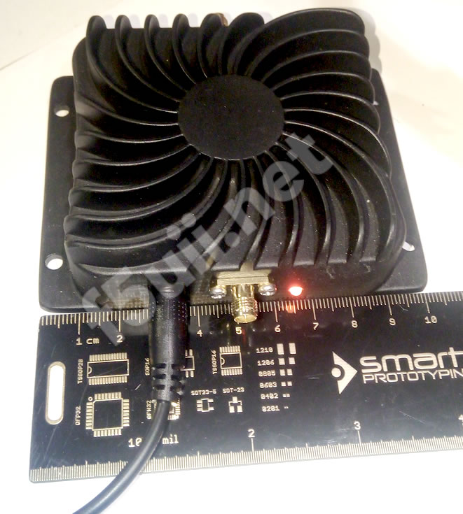
Le LimeSDR mini est stable et n’a pas besoin de modification de son VCTCXO. Il réagira tout de même à une variation brusque de température (en lui soufflant dessus) mais revient très bien et rapidement ( 2s) à sa fréquence nominale. C’est le LimeSDR mini que j’ai emporté en FY pour la première activation sur QO100. Il peut tout de même faire l’objet d’une injection de signal externe comme celui provenant d’un GPSDO et dans ce cas, une modification doit être apportée sur 2 résistances (enlever R59 et souder R62). Je n’ai pas eu besoin de mettre cela en place et trafique avec le LimeSDR mini en SSB et DATV. Pour que le limeSDR mini ne surchauffe pas, il vous faut ajouter une ventilation et à minima quelques petits radiateurs.
J’ai eu l’occasion de présenter un tableau comparatif entre les 2 émetteur SDR LimeSDR mini et Adalm pluto, que j’apprécie d’utiliser l’un et l’autre.
Je vous invite à regarder mon support de présentation page 31 (uniquement en langue française) ou la video de la conférence de l’Amsat-F de mars 2020.
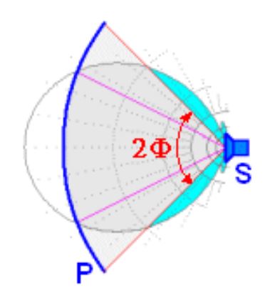
Concernant l’éclairement d’une parabole, j’ai eu l’occasion de l’évoquer lors d’une autre conférence (Vidéo et support de présentation : Strasbourg de janvier 2020 – page 48). Une source à placer au foyer d’une parabole, sera optimale (en terme de rendement et donc de gain) lorsque son lobe de rayonnement sera d’une ouverture telle qu’elle apporte un niveau de -10dB au bord de la parabole. Cela dépend donc de votre parabole et de son rapport f/D (distance focale / diamètre). Avec l’hélice, il est facile de déterminer l’angle de rayonnement à -10 dB puisque cela dépend du nombre de spire. Un patch Poty ou autre (DC5GY, DJ7GP…) sont fixe et plutôt plus large que nécessaire si vous utiliser une parabole offset. Mais bien-sûr, cela fonctionne tout à fait bien à l’émission. Concernant la réception sur une Poty, le guide d’onde permet d’apporter le signal 10 GHz au LNB placé au delà du foyer. Une très petite atténuation peut exister mais n’est pas problématique (surtout pas en SSB).
Mes 73, et à bientôt pour un QSO sur QO-100. Christian
(Translation)
Hello, Henri,
The LimeSDR mini is stable and does not require any modification to its VCTCXO. It will still react to a sudden change in temperature (by blowing on it) but returns very well and quickly (2s) to its nominal frequency. This is the LimeSDR mini that I brought in FY for the first activation on QO100. It can nevertheless be injected with an external signal like the one coming from a GPSDO and in this case, a modification must be made on 2 resistors (remove R59 and solder R62). I didn’t need to set this up and worked with the LimeSDR mini in SSB and DATV. To prevent the LimeSDR mini from overheating, you need to add ventilation and at least a few small radiators.
I had the opportunity to present a comparison table between the 2 SDR transmitters LimeSDR mini and Adalm pluto, which I like to use both.
I invite you to watch my presentation support on page 31 (only in French language) or the video of the Amsat-F conference of March 2020.
Concerning the illumination of a parabola, I had the opportunity to talk about it during another conference (Video and presentation support: Strasbourg of January 2020 – page 48). A feed to be placed at the focus of a parabola, will be optimal (in terms of output and therefore gain) when its radiation lobe is of such an opening that it brings a level of -10dB at the edge of the parabola. This depends on your dish and its f/D ratio (focal length/diameter). With the helix, it is easy to determine the radiation angle at -10dB since it depends on the number of turns. A Poty patch or other (DC5GY, DJ7GP…) are fixed and rather wider than necessary if you use an offset dish. But of course, this works quite well for transmission. Concerning the reception on a Poty, the waveguide makes it possible to bring the 10 GHz signal to the LNB placed beyond the focus. A very small attenuation can exist but is not problematic (especially not in SSB).
73, and see you soon for a QSO on QO-100. Christian
Bonjour Christian,
Je vous remercie pour vos réponses claires et détaillées.
Elles vont me permettre de faire un choix pour les premiers essais.
73, F6IAX Henri
(Translation)
Hello, Christian,
Thank you for your clear and detailed answers.
They will allow me to make a choice for the first tests.
73, F6IAX Henri
Bonjour Christian,
Merci pour cet immense travail de documentation, explication qui m’a permis de me lancer dans la réception QO-100 à partir d’un RSP2 + parabole EDENWOOD 65cm + LNB PLL Avenger le tout relié à la station avec 25m de câble H100 et piloté par SDRUNO, ça fonctionne bien, maintenant j’envisage l’émission, je pense passer par mon yaesu FT736R + Transverter DXPATROL + Filtre TAGLOAS + Ampli EDUP-EP-AB003 + Antenne DuoBand-Feed 2.4 & 10 GHz avec LNB.
Cette configuration me permettrai de conserver mon RSP2 et SDRUNO en réception.
Toutefois j’hésite avec le tout SDR émission-réception SDRUNO +LIMEmini +filtre TAGLOAS+Ampli EDUP-EP-AB003 + Antenne DuoBand-Feed avec LNB, tout en gardant la même parabole et la même distance de la station.
Avez une opinion sur le choix de configuration ?
La parabole me semble pour l’émission peut être un peu petite ?
La distance entre parabole et station (25m) peut être un peu grande ?
Votre expérience va beaucoup m’aider
Cordialement
73’s de F1MCF Thierry
(Translation)
Hello, Christian,
Thank you for this huge documentation work, explanation which allowed me to start receiving QO-100 from a RSP2 + EDENWOOD 65cm dish + LNB PLL Avenger all connected to the station with 25m of H100 cable and controlled by SDRUNO, it works well. Now I’m considering the broadcast, I think I’ll go through my yaesu FT736R + DXPATROL Transverter + TAGLOAS Filter + EDUP-EP-AB003 Amplifier + DuoBand-Feed 2.4 & 10 GHz antenna with LNB.
This configuration will allow me to keep my RSP2 and SDRUNO in reception.
Anyway I hesitate with the whole SDR transmit-receive SDRUNO +LIMEmini + TAGLOAS filter+Ampli EDUP-EP-AB003 + DuoBand-Feed Antenna with LNB, while keeping the same dish and the same distance from the station.
Have an opinion on the choice of configuration?
The dish seems to me for the broadcast may be a little small?
The distance between dish and station (25m) can be a bit big?
Your experience will help me a lot
Sincerely
73’s of F1MCF Thierry
Bonjour Christian,
petite correction j’utilise SDR console pour le pilotage du RSP2 quand j’écoute QO-100
73’s
Thierry
(Translation)
Hello, Christian,
small correction I use SDR console for RSP2 control when I listen to QO-100
73’s
Thierry
Bonjour Thierry,
Les 25m de câble sont évidemment un handicap si aucun émetteur/PA ne peut être placé plus proche de la parabole.
Avec un câble faible perte, tel un Ecoflex 15+, il y a 15 dB de perte au 100m sur 2400MHz. Pour 25m, cela atteint tout de même à minima 4 dB de pertes (+/- pertes de connectique). Avec l’EDUP 007 qui sort 3,5W max soit 35.4 dB, vous aurez 31.4dB, soit 1.4W au mieux disponible. Sachant que votre parabole est une offset de 65cm,et que le diagramme de rayonnement d’une POTY est plus large que « nécessaire » (f/D – voir ma conférence de Strasbourg), cela pourra fonctionner, mais pas avec le signal ne sera évidemment pas très imposant. Votre trafic SSB restera exploitable à la réception en descente du satellite, en CW aucun problème. L’optimum serait de placer le tout au plus proche de la parabole. Vous évoquez une solution SDR. Pour cela, l’Adalm pluto qui peut être mis sur réseau permet cela plus facilement que le limeSDR, ou un câble USB actif est nécessaire (comme celui-ci). Mon dernier article sur la DVB détaille les possibilités et contraintes du PlutoSDR.
A bientôt sur QO-100 , 73 F5UII
(Translation)
Hello Thierry,
The 25m cable is obviously a handicap if no transmitter/PA can be placed closer to the dish.
With a low-loss cable, such as an Ecoflex 15+, there is 15 dB of loss at 100m on 2400MHz. For 25m, this still reaches at least 4 dB of loss (+/- connector losses). With the EDUP 007 which outputs 3.5W max or 35.4dB, you will have 31.4dB, or 1.4W at best available. Knowing that your dish is an offset of 65cm, and that the radiation pattern of a POTY is wider than “necessary” (f/D – see my conference in Strasbourg), it could work, but not with the signal will obviously not be very imposing. Your SSB traffic will still be readable downlink reception, in CW no problem. The optimum would be to place it as close as possible to the dish. You are talking about an SDR solution. For this, the Adalm pluto which can be connected to the IP network allows this more easily than the SDR file, where an active USB cable is required (like this one). My last article on DVB details the possibilities and constraints of PlutoSDR.
Soon on QO-100, 73 F5UII
Bonjour Christian,
Merci pour votre retour, j’avais déjà téléchargé votre conférence de Strasbourg, vos commentaires vont bien m’aider.
Je vais installer l’ensemble émission au plus prêt de la parabole, en utilisant le PlutoSDR, je vais de ce pas lire votre article sur le PlutoSDR.
Le projet est pour cet automne, le temps de le maturer et de le réaliser.
A bientôt sur QO-100 que j’écoute pour le moment ou sur une fréquence VHF ou HF.
Cordialement avec mes 73’s
Thierry
(Translation)
Hello, Christian,
Thank you for your feedback, I had already downloaded your Strasbourg conference, your comments will help me a lot.
I’m going to install the broadcast set as close as possible to the dish, using PlutoSDR, I’ll read your article about PlutoSDR right away.
The project is for this autumn, the time to mature and realize it.
See you soon on QO-100 that I’m listening to at the moment or on a VHF or HF frequency.
Sincerely with my 73’s
Thierry
Bonjour Christian,
Tout d’abord merci pour ces nombreux tutos, plus que nécessaire, pour les OM comme moi possédant de faibles connaissances en informatique !
J’ai bien suivi votre QSO samedi 30 mai vers 14h00 avec la station CU2, S9 de part et d’autre avec une très bonne qualité de modulation.
La partie RX de ma SDR console fonctionne très bien. Sur la partie TX je rencontre un problème. Le delta à l’émission est programmé mais je ne peut pas émettre un tone/un tune/encore moins avec le micro. En fait rien n’apparait dans la fenêtre “spectrum” même pas la “trace verte ! Comme si cette fenêtre n’était pas activée ? Sur mon précédent ordinateur en windows 7 je n’ai pas eu ce problème, mais il manquait de ressource pour faire tourner correctement du SDR. Maintenant je suis en windows 10 sur un Lenovo.
Avez-vous une idée Christian pour résoudre ce problème, merci d’avance pour votre réponse.
J’espère pouvoir vous rejoindre très rapidement via le transpondeur de QO100.
73’s et bon trafic.
Pierre F5MUF QTH nr Lille
(Translation)
Hello, Christian,
First of all thank you for these many tutorials, more than necessary, for OM like me with little computer knowledge!
I did follow your QSO on Saturday May 30th around 2pm with the CU2, S9 station on both sides with a very good modulation quality.
The RX part of my SDR console works very well. On the TX part I have a problem. The delta on the show is programmed but I can’t emit a tone/tune/anything less with the microphone. In fact nothing appears in the “spectrum” window, not even the “green trace”! As if this window was not activated? On my previous computer in Windows 7 I didn’t have this problem, but it lacked the resources to run SDR correctly. Now I am in windows 10 on a Lenovo.
Do you have an idea Christian to solve this problem, thank you in advance for your answer.
I hope to be able to join you very quickly via the transponder of QO100.
73’s and good traffic.
Pierre F5MUF QTH nr Lille
Bonjour Pierre,
Difficile de répondre sans capture d’écran et surtout sans connaitre l’émetteur récepteur SDR utilisé. S’il s’agit d’un LimeSDR, une piste est de vérifier au lancement, dans la fenêtre Select Radio, que vous choisissez bien la bonne largeur de spectre (Bandwith) qui est précisé TX. Il n’y en a qu’une seule de disponible et qui ouvre la possibilité de passer en émission.
A bientôt sur QO-100. 73
(Translation)
Hello Pierre
Difficult to answer without a screenshot and especially without knowing the SDR transceiver used. If it is a LimeSDR, one track is to check at launch, in the Select Radio window, that you choose the appropriate spectrum width (Bandwith) which is specified TX. There is only one of these available and it opens the possibility to switch to transmission.
See you soon on QO-100. 73
Bonjour Christian,
Merci beaucoup pour votre réponse, effectivement difficile de répondre avec les manques de données.
Pour avancer dans cette difficulté voici un complément d’information.
Je travaille avec:
– Adalm Pluto
– sur select radio j’ai paramétré = converter down : 9750 MHz/8089.5 MHz
bandwidth : 550 KHz
– dans la fenêtre RX1 (delta pointe en bas) apparait 9750 MHz
– dans la fenêtre TX (delta pointe en haut) apparait 8089.5 HHz
Voilà, et dans cette configuration impossible de passer à l’émission: ni en tune, ni en tone, ni en micro !
Je ne sais pas si d’autres OM ont été confrontés à ce type de problème ?
Nous cherchons à plusieurs OM du 59 en même temps.
Par ailleurs vous avez les 73’s de Bernard F1AEQ (mon beau-frère) dans votre région, HI !
Nous voyons ensemble et merci d’avance Christian.
73’s QRO
Pierre F5MUF
(Translation)
Hello, Christian,
Thank you very much for your answer, indeed difficult to answer with the lack of data.
In order to advance in this difficulty, here is some more information.
I work with:
– Adalm Pluto.
– on select radio I set = converter down: 9750 MHz/8089.5 MHz
bandwidth: 550 KHz
– in the RX1 window (delta point down) appears 9750 MHz
– in the TX window (delta point up) appears 8089.5 HHz
That’s it, and in this configuration, it’s impossible to switch to the show: neither in tune, nor in tone, nor in microphone!
I don’t know if other OMs have faced this kind of problem?
We are looking for several OMs from 59 at the same time.
Besides you have Bernard F1AEQ’s 73’s (my brother-in-law) in your area, HI!
We check together and thank you in advance Christian.
73’s QRO
Pierre F5MUF
Pierre,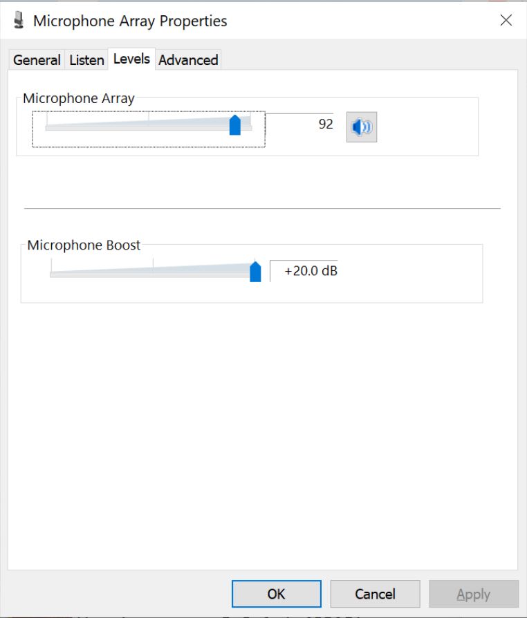
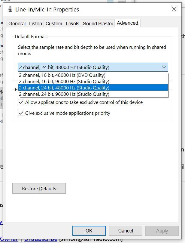
Le paramétrage des splits en fréquences de réception et émission correspondent à ce qui est attendus. Le souci doit effectivement être lié à l’entrée son. Il faut tester avec différentes entrées qui peuvent être disponible sur votre carte son (microphone, mixer, entrée line). En dehors de SDR Console, vérifier le bon fonctionnement de l’entrée microphone sur le panneau de réglage Windows. Il peut être nécessaire d’activer la fonction Boost ou ‘ampli’ sur les entrées microphone pour que les niveaux soient suffisant et exploitable. Eventuellement utiliser une carte son externe USB comme celle-ci pour tester, ou un câble audio virtuel. A tester avec la fonction monitor, et bouton RX activé.
Le fait que le Tune ne donne rien, pourrait par contre être un problème d’accès aux périphériques d’entrée audio. J’ai lu fin mai 2020 que certaines cartes son (Realtek par exemple) proposent des entrées microphones multi canaux, et pour lesquels SDR Console n’était pas encore capable de les gérer. Mais là, c’est déjà un cas particulier.
OK pour Bernard, on se contacte régulièrement.
73 Christian
(Translation)
Pierre,
The settings of the splits in receive and transmit frequencies correspond to what is expected. The concern must indeed be related to the sound input. You should test with different inputs that may be available on your sound card (microphone, mixer, line input). Outside SDR Console, check the correct operation of the microphone input on the Windows control panel. It may be necessary to activate the Boost or ‘amp’ function on the microphone inputs for the levels to be sufficient and usable. Possibly use an external USB sound card like this one for testing , or a virtual audio cable. To test with the monitor function, and RX button enabled.
The fact that the Tune doesn’t give anything, on the other hand, could be a problem of access to the audio input devices. I read at the end of May 2020 that some sound cards (Realtek for example) offer multi-channel microphone inputs, and for which SDR Console was not yet able to manage them. But this is already a special case.
OK for Bernard, we contact each other regularly.
73 Christian
Bonjour et bravo pour votre site, il est devenu la référence pour qui veut trafiquer sur Oscar 100 !
Ayant réussi l’examen RA il y a quelques semaines, je suis en train de remplir la demande d’indicatif personnel ainsi que le tableau des P.A.R en fonction des gammes de fréquence.
J’ai commencé a monter une station sur QO100 comprenant un adalm pluto associé à SDR console. Une parabole 70 cm comprenant le LNB et une antenne hélice de 5 tours (environ 11dB).
Je me pose la question suivante concernant la PAR en émission à 2.4GHz en utilisant une antenne hélice devant une parabole : Après avoir déduit les pertes dues aux câbles coaxial, le gain de l’antenne hélice et le gain de la parabole s’ajoutent ils ? Le gain donné pour une parabole de 70 cm (environ 22dB) est le gain donné en réception à 10Ghz, est ce le même gain à 2.4GHz ?
(Translation)
Hello and bravo for your site, it has become the reference for anyone who wants to work on Oscar 100!
Having passed the RA exam a few weeks ago, I’m currently filling out the P.A personal callsign request as well as the P.A.R. table according to frequency ranges.
I’ve started to set up a station on QO100 with an adalm pluto associated with SDR console. A 70 cm dish including the LNB and a 5-turn helix antenna (about 11dB).
I ask myself the following question about PAR transmitting at 2.4GHz using a helix antenna in front of a dish: After deducting the losses due to the coaxial cables, do the gain of the helix antenna and the gain of the dish add up? The gain given for a 70cm dish (about 22dB) is the gain given in reception at 10Ghz, is it the same gain at 2.4GHz?
Bonjour,
Tout d’abord merci pour vos mots d’encouragement.
 .
.
Le gain d’une parabole répond a cette formule.
Le gain isotrope va dépendre principalement de la longueur et du diamètre. Ensuite, cela dépend de l’efficacité de la source à bien illuminer la parabole, et de la qualité mécanique (précision de la forme parabolique) et continuité électrique. Ces éléments correspondent au coefficient k de la formule. Une hélice bien positionnée, avec le bon angle d’éclairement, améliorera le coefficient k. La convention veut que l’hélice est son lobe de -10 dB sur le pourtour de la parabole. Donc on n’ajoutera jamais le gain d’une hélice au gain d’une parabole pour considéré le gain total !
.
Le gain d’une parabole de 0.7m sur 10,5GHz avec un coefficient k =0.7 a un gain normalement plus autour de 35dB que de 22dB Je vous invite à vérifier cette caractéristique.
On convertit aisément le gain d’une parabole donnée à une fréquence sur une autre. On trouve +/- 12.7 db de moins de gain sur 2400 MHZ pour une parabole qui aurait un gain de 35dB sur 10250 MHz, soit +/- 22,3dB.
Pour vérifier le gain d’une parabole Offset et déterminer le nombre de spires d’une source en hélice correspondant précisément aux dimensions de parabole offset, je vous conseille l’excellent tableau excel de F6AGR (à télécharger depuis ce commentaire ). Il vous donnera un gain théorique de cette installation.
Au plaisir d’un QSO sur QO100, j’espère.
(Translation)
Hello,
First of all, thank you for your words of support.
 .
.
The gain of a parabola answers this formula.
The isotropic gain will depend mainly on the wave length and diameter. Then, it depends on the efficiency of the source to illuminate the parabola well, and on the mechanical quality (precision of the parabolic shape) and electrical continuity. These elements correspond to the coefficient k of the formula. A well positioned helix, with the right illumination angle, will improve the k coefficient. The convention is that the helix is its -10 dB lobe on the periphery of the parabola. So we will never add the gain of a helix to the gain of a dish to consider the total gain !
The gain of a 0.7m parabola on 10.5GHz with a coefficient k =0.7 has a gain normally more around 35dB than 22dB I invite you to check this characteristic.
It is easy to convert the gain of a given dish at one frequency to another. We find +/- 12.7 db less gain on 2400 MHZ for a dish that would have a gain of 35dB on 10250 MHz, i.e. +/- 22.3dB.
To check the gain of an Offset dish and determine the number of turns for a helix feed corresponding precisely to the offset dish dimensions, I recommend the excellent excel table from F6AGR (to download from this comment ). It will give you a theoretical gain of this setup.
Hopefully a QSO on QO100.
Merci de votre réponse, c’est parfaitement clair !
Bonne continuation et au plaisir de se retrouver sur QO100.
Cordialement,
Fabrice
(Translation)
Thank you for your answer, it’s perfectly clear!
Good continuation and see you on QO100.
Sincerely,
Fabrice
Bonjour,
Je tente de mesurer la puissance de sortie de mon adalm pluto à partir d’un petit wattmetre chinois 8Ghz à base d’AD8318.
A 2.4GHz, FM et drive à 100% depuis SDR console, attenuateur 20db, je suis surpris de mesurer 6.4 dbm. Le pluto est connu pour sortir entre 2 et 3 dbm, à votre avis d’ou vient l’erreur, d’autre OM utilisent ils ce mini wattmetre RF et obtiennent de bon résultats ?
(Translation)
Hello,
I try to measure the output power of my adalm pluto from a small Chinese 8Ghz wattmeter based on AD8318.
At 2.4GHz, FM and 100% drive from SDR console, 20db attenuator, I am surprised to measure 6.4 dbm. The pluto is known to output between 2 and 3 dbm, where do you think the error comes from, do other OM use this mini RF wattmeter and get good results ?
Bonjour Fabrice,
Tout d’abord félicitation pour votre indicatif tout récent.
Comme je l’ai indiqué lors de ma conférence AMSAT-F de début 2020, au chapitre 3 émission, lors d’un comparatif Adalm Pluto/LimeSDR, le niveau peut attendre avec SDR Console 6 dBm. Pour atteindre ce niveau, la case Boost est cochée. Les relevés sont réalisés en tune CW.
A bientôt sur QO100.
73 Christian
(Translation)
Hello Fabrice,
First of all, congratulations for your most recent callsign.
As I mentioned at my AMSAT-F conference in the beginning of 2020, in chapter 3 emission, in a comparison of Adalm Pluto/LimeSDR, the level can be expected with SDR Console 6 dBm. To reach this level, the Boost checkbox is checked. The readings are made in CW tune.
See you soon on QO100.
73 Christian
Bonjour Christian,
J’ai persévéré dans mes recherches et j’ai décidé de construire mon propre wattmetre RF toujours à base D’AD8318. Je me suis inspiré d’un montage réalisé par le youtubeur Électro-Bidouilleur à base de STM32. Si cela vous intéresse vous pouvez avoir un aperçu sur QRZ.com et mon indicatif F4IPT.
Les mesures réalisées sont tout à fait en accord avec les spécifications attendues de l’adalm pluto. Ce qui me fait penser que le wattmetre chinois cité précédemment n’est pas juste du moins à 2.4GHz.
Meilleurs 73s,
Fabrice
(Translation)
Hello Christian,
I persevered in my research and decided to build my own RF wattmeter still based on AD8318. I was inspired by a montage made by the youtubeur Électro-Bidouilleur based on STM32. If you are interested you can have a look on QRZ.com and my F4IPT callsign.
The measurements made are completely in accordance with the specifications expected from adalm pluto. What makes me think that the Chinese wattmeter quoted above is not right at least at 2.4GHz.
Best 73s,
Fabrice
Bonsoir à tous,
Pour QO100 bande étroite j’utilise le Pluto et SDR Console.
Je trouve que le spectre RF de sortie du Pluto est assez moyen avec des raies dans les 42 dB en dessous de la porteuse. Cela dépends assez peu du niveau de sortie.
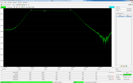
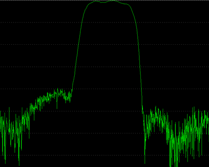
Je me demande si d’autres OMs ont regardé le signal de sortie avec un analyseur de spectre?
J’ai deux photos du spectre avec un span de 500 KHz et 5 MHz.
73 jacques F6BKI
(Translation)
Good evening to all,
For QO100 narrow band I use Pluto and SDR Console.
I find that the output RF spectrum of the Pluto is quite average with lines in the 42 dB below the carrier. This depends very little on the output level.
I wonder if other OMs have looked at the output signal with a spectrum analyser?
I have two pictures of the spectrum with a span of 500 KHz and 5 MHz.
73 jacques F6BKI
Jacques,
Oui cela a été constaté par d’autres, et d’ailleurs sur nouveau système LEILA-2 qui utilise l’Adalm Pluto génère un signal non désiré et visible à la descente de QO100. Je t’invite à regarder les explications de Mario DL5MLO, concepteur de LEILA à ce sujet et aborder lors du dernier Symposium de l’AMSAT-DL. 73 Christian
(Translation)
Jacques,
Yes, this has been noticed by others, and moreover on the new LEILA-2 system using Adalm Pluto generates an unwanted and visible signal when descending from QO100. I invite you to take a look at the explanations of Mario DL5MLO, designer of LEILA on this subject and discuss at the last AMSAT-DL Symposium. 73 Christian
Bonjour Christian,
Merci pour le temps passé à nous décortiquer les éléments TX/RX pour pouvoir trafiquer sur ce satellite. J’ai une question qui concerne le Lime SDR mini, je voulais savoir si vous aviez constaté une dérive fréquentielle à l’émission (avec les +/-4ppm annoncé)?, c’est toujours mieux que le Pluto hors correction à 25ppm….
si oui, utilisez vous une source externe pour stabiliser la fréquence ou nul besoin?
73,
F1SGR. Vincent
(Translation)
Hello Christian,
Thank you for the time spent to dissect the TX/RX elements to be able to work on this satellite. I have a question concerning the Lime SDR mini, I wanted to know if you have noticed a frequency drift at the emission (with the +/-4ppm announced), it is still better than the Pluto without correction at 25ppm….
if yes, do you use an external source to stabilize the frequency or no need?
73,
F1SGR. Vincent
Bonjour Vincent,
D’expérience, le LimeSDR Mini mis en boitier ventilé, il n’y a pas de dérive en fréquence remarquable et gênante. Le VCTCXO est placé sous la platine.
En soufflant de l’air chaud sur le VCTCXO, la fréquence d’émission est très vite modifié, mais celle-ci revient en position initiale avant perturbation en quelques secondes.
Autrement dit, j’ai utilisé le limemini en SSB sans référence externe, sans difficulté pour les correspondant.
73
Christian
(Translation)
Hello Vincent,
In my experience, the LimeSDR Mini in a ventilated case does not show any noticeable and annoying frequency drift. The VCTCXO is placed under the board.
By blowing hot air on the VCTCXO, the emission frequency is very quickly modified, but it returns to its initial position same as before disturbance in a few seconds.
In other words, I used the limemini in SSB without external reference, without any difficulty for the correspondents.
73, Chris
Hello Christian,
Merci pour ton retour, dis moi, le LimeSDR (mini ou non) est full duplex?
73
(Translation)
Hello Christian,
Thanks for your feedback, tell me, is the LimeSDR (mini or not) full duplex?
73
Oui, les LimeSDR sont capables de fonctionner en full-duplex, réception et émission simultanée
(Translation)
Yes, LimeSDRs are designed to operate in full-duplex, simultaneous receive and transmit
Bonjour Christian,
Merci pour le site et son aide précieuse!
Je viens de terminer ma station qo100 avec le PLUTO, un GPSDO et SDR Console.
Lorsque je suis en mode Full Duplex et en émission, je ne reçois plus aucun signal pourtant SyncRX est bien selectionné et dès que je coupe l’émission j’entends la fin de mon émission.
Est-ce que c’est un problème de débit réseau (j’ai une partie en wifi)? ou un problème de configuration?
Pour info mon antenne est une parabole 80cm avec LNB et antenne hélicoïdale 3 tours
Manu F4HSE
(Translation)
Hello Christian,
Thank you for the site and its precious help!
I just finished my qo100 station with the PLUTO, a GPSDO and SDR Console.
When I am in Full Duplex mode and transmitting, I do not receive any signal although SyncRX is well selected and as soon as I cut the transmission I hear the end of my transmission.
Is it a network speed problem (I have a part in wifi) or a configuration problem?
For info my antenna is an 80cm dish with LNB and 3 tower helical antenna
Manu F4HSE
Bonjour Manu,
Je comprends que le même le bruit de planché du satellite baisse durant la transmission. Si tu es sur d’avoir cocher Full-duplex (Dans le panneau Receive, Transmit = Full-duplex), il pourrait s’agir d’une gêne de l’émission 2.4GHz qui perturbe le fonctionne du LNB qui se trouve être au foyer de la parabole.
Essayer peut-être diminuer la puissance d’émission pour voir si ce phénomène disparait sous un certain seuil.
Tu peux en attendant, faire la réception durant la transmisssion depuis un récepteur déporté sur internet (WebSDR https://eshail.batc.org.uk/nb)
Impatient de te saluer via QO-100. 73 Christian
(Traduction)
Hello Manu,
I understand that even the satellite floor noise drops during transmission. If you are sure you have checked Full-duplex (In the Receive, Transmit = Full-duplex panel), it could be a 2.4GHz transmission that is interfering with the LNB that is at the focus of the dish.
Maybe try to decrease the transmission power to see if this phenomenon disappears under a certain threshold.
In the meantime, you can do the reception during the transmission from a remote receiver on the internet (WebSDR https://eshail.batc.org.uk/nb)
I look forward to greeting you via QO-100. 73 Christian
Christian,
Je vais essayé ta suggestion.
J’ai fait quelques tests supplémentaire en me connectant en USB directement sur le Pluto: le résultat est le même.
Pour info je n’ai pas de filtre 2.4Ghz avant l’ampli. Est-ce que cela pourrait être la cause?
Effectivement j utilise un WebSDR mais je trouve que ce n’est pas pratique, il faut changer a chaque fois 2 fréquences!! avec l âge on devient exigeant! et le but est de faire une station portable pour les vacances.
(Translation)
Christian,
I will try your suggestion.
I did some additional tests by connecting directly to the Pluto via USB: the result is the same.
For your information I don’t have a 2.4Ghz filter before the amp. Could this be the cause?
Indeed I use a WebSDR but I find that it is not practical, it is necessary to change each time 2 frequencies! with the age one becomes demanding! and the goal is to make a portable station for the vacations.
Bonjour,
Je voudrais me servir de la partie réception sur 433 Mhz (DB6NT) et 144 voie montante (suivi d’un convertisseur DX PATROL).
Je veux asservir les deux, je ne trouve pas la fonction.
Pouvez vous me venir en aide.
73 amitiés F4DLO
(Translation)
Hello,
I would like to use the reception part on 433 Mhz (DB6NT) and 144 upstream (followed by a DX PATROL converter).
I want to slave the two, I can’t find the function.
Can you help me.
73 F4DLO regards
Vous allez suivre le même paramétrage que ce que vous lisez dans mon article L’émission vers le satellite Qatar Oscar 100 avec SDR Console mais en transposant les fréquences utilisées à la réception et à l’émission.
Bonne configuration
(Translation)
You will follow the same setup as what you read in my article The transmission over Qatar Oscar 100 satellite with SDR Console but transposing the frequencies used for receiving and transmitting.
Good configuration
Bonjour Christian,
félicitations pour tout ce beau travail et explications.
Je cherche a faire fonctionner SDRConsole en CW “auto” mais impossible de trouver la configuration pour le passage en PTT. Ca fait des semaines que je cherche et je teste en vain…
J’ai vu que certains utilise Fldigi mais ca ne fonctionne pas non plus chez moi.
J’ai MRP40 qui est très simple pourtant , CW Machine de Logger32 mais impossible a faire fonctionner en PTT.
Aurais tu une idée ?
Merci d’avance.
73 de Flo F4EJL
(translation)
Hello Christian,
congratulations for all this great work and explanations.
I’m trying to get SDRConsole to work in CW “auto” but I can’t find the configuration for switching to PTT. I’ve been looking for weeks and testing in vain…
I’ve seen that some people use Fldigi but that doesn’t work for me either.
I have MRP40 which is very simple though, CW Machine from Logger32 but impossible to make work in PTT.
Would you have an idea?
Merci d’avance.
73 from Flo F4EJL
Bonsoir
J’ai repris la station QO-100 d’un OM décédé basé sur un Lime SDR
j’ai installé le driver du Lime comme indiqué sur votre site
il est bien reconnu dans SDR Console
j’ai configuré SDR Console comme indiqué sur le site
j’ai bien pointé la parabole sur QO-100 j’ai vérifié avec une autre station
mais je n’est aucune réception je ne vois pas la balise
y a t’il un autre moyen de tester le Lime SDR
73 Camille F6HRO
—
(Translation)
Good evening. I took over the QO-100 station from a deceased OM based on a Lime SDR. I installed the Lime driver as indicated on your website. It is recognized in SDR Console. I configured SDR Console as indicated on the website. I pointed the dish at QO -100. I checked with another station, but I have no reception and cannot see the beacon. Is there another way to test the Lime SDR?
73 Camille F6HRO
Merci Camille pour votre message. Si le LimeSDR est bien reconnu dans SDR Console mais que tu ne reçois pas la balise, voici quelques vérifications et tests à faire :
– Essayer la réception sur un signal local VHF par exemple (attention à la force des signaux)
– Vérifier le LNB: s’assurer qu’elle est bien alimentée
– LimeSuiteGUI avec LimeUtil peut vous à faire des tests sur le LimeSDR pour aller plus loin
(Translation)
Thank you Camille for your message. If the LimeSDR is recognized in SDR Console but you are not receiving the beacon, here are some checks and tests to perform:
– Try receiving on a local VHF signal, for example (pay attention to signal strength)
– Check the LNB: make sure it is properly powered
– LimeSuiteGUI with LimeUtil can help you run tests on the LimeSDR to get more information